– 2.10 –
2-1-7. HDC-2Head PCB
This board is located under the HDC-4Head PCB in the electrical equipment case. It receives
signals from the main PCB, generates the COM signal for driving heads 5 and 6, generates
nozzle data, and transfers each data to the slider PCB through the FPC cable.
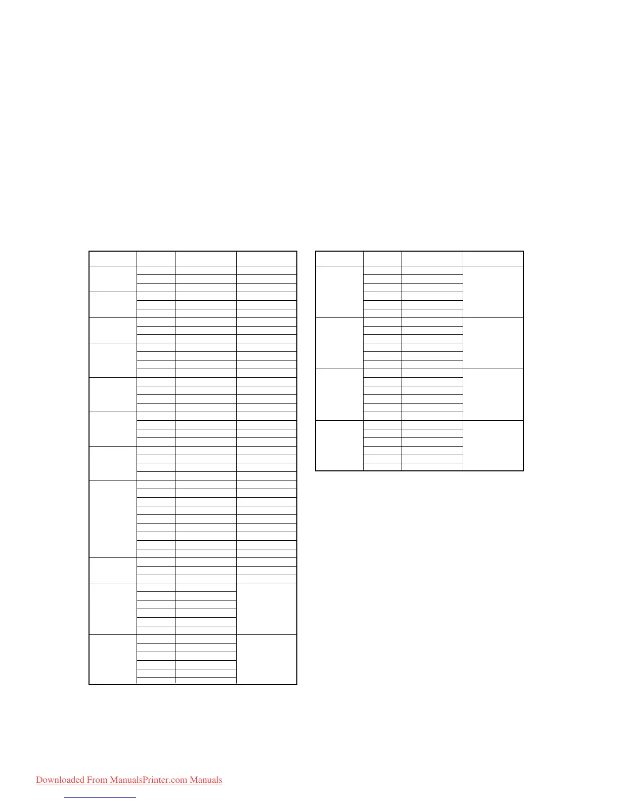
2-1-8. IO PCB
This board is located on the back of the right frame. It receives the signal of each sensor,
transfers each data to the main PCB, and controls various stepping motors and take-up motors.
IO PCB Connector signals
Connector Pin No. Signal Name Remarks
1 +5V
2D0 Origins
3 GND
1 +5V
2D1 Lever sensor
3 GND
1 +5V
2D2 Paper sensor
3 GND
1 +5V
2D3 Station sensor
3 N.C.
4 GND
1 +5V
2D4Wiper sensor
3 N.C.
4 GND
1 POWER-F
2 POWER-F
1 POWER Not used
2 /POWER
1 POWER-M Take-up motor
2 POWER-M Take-up motor
3 +5V
4W-ENC Not used
5W-SEN Not used
6 GND
7 GND
8W-UNIT Not used
9 GND
1 POWER-L
2 GND
3 LAMP Not used
1 MA-P1
2 N.C.
3 /MA-P1
4 MB-P1
5 N.C.
6 /MB-P1
1 MA-P2
2 N.C.
3 /MA-P2
4 MB-P2
5 N.C.
6 /MB-P2
CN2
CN14
CN3
CN4
CN5
CN6
CN7 /
8/ 9/ 10
CN11 /
12/ 15/ 28
CN17
Connector Pin No. Signal Name Remarks
1 MA-P3
2N.C.
3 /MA-P3
4 MB-P3
5N.C.
6 MB-P3
1 MA-P4
2N.C.
3 /MA-P4
4 MB-P4
5N.C.
6 /MB-P4
1 MA-WP
2N.C.
3 /MA-WP
4 MB-WP
5N.C.
6 /MB-WP
1 MA-CP
2N.C.
3 /MA-CP
4 MB-CP
5N.C.
6 /MB-CP
CN24
CN25
CN26
CN27
CN22
CN23
Pump motor 1
Pump motor 2
Pumop motor 3
Pumop motor 4
Wiper motor
Capping motor
Downloaded From ManualsPrinter.com Manuals
 Loading...


