© 2009 MIMAKI ENGINEERING CO.,LTD.
6.5.12 P.2
6.5.12 Encoder PCB Assy
1
2
3
4
5
6
7
8
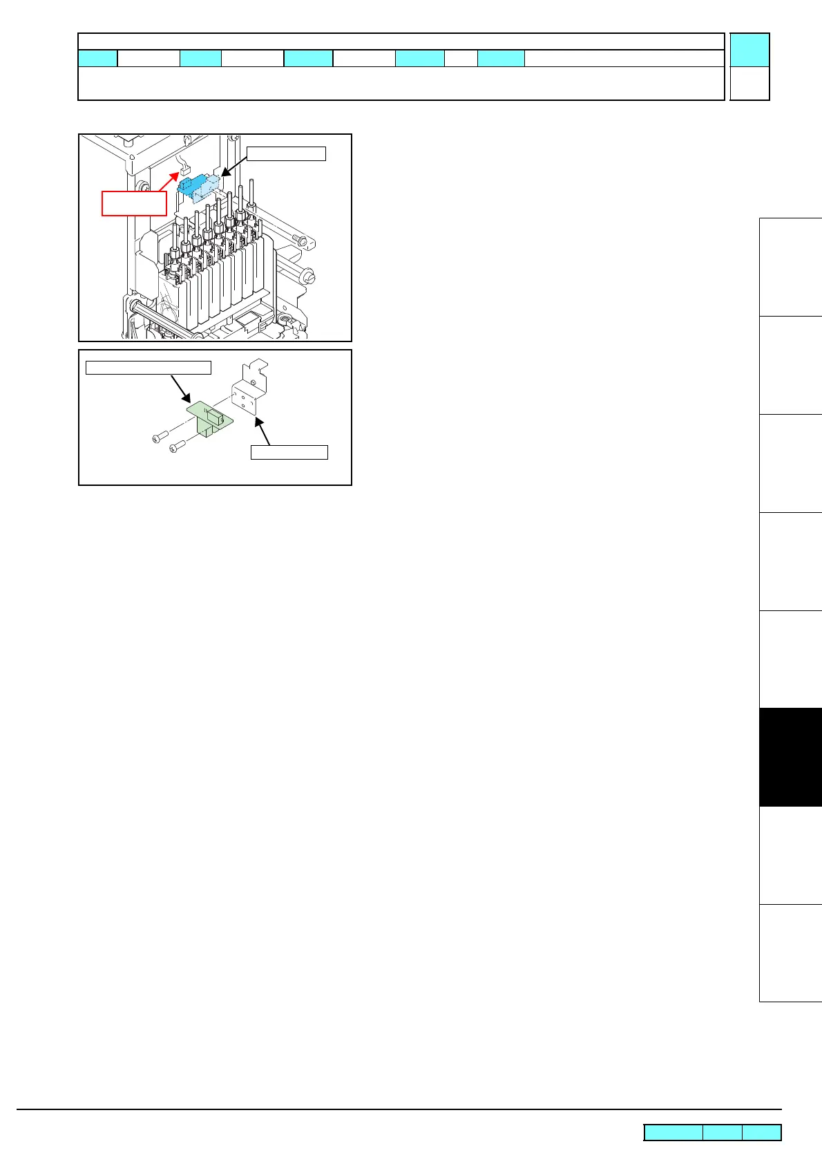
4. Insert a driver through the gap of the damper to loosen the
screws, remove the encoder PCB assy together with L sensor
BKT, and then release the connector.
5. Remove the encoder PCB assy.
6. Reverse the disassembly procedure for reassembly.
L Sensor BKT
Releasing
connector
Encoder PCB Assy
L Sensor BKT
R.1.1
Maintenance Manual > Disassembly and Reassembly > Electrical Parts > Encoder PCB Assy
Model CJV30/TPC Issued 2008.08.04 Revised 2008.09.17 F/W ver. 1.20 Remark
1.1

 Loading...


