Calibration
The calibration is an operation that matches the
actual load of the sensor to the display of
CSD-709 to display the electrical signal from the
sensor (load cell) as an accurate load.
Status display LED
SEL1 SEL2
Calibration
number
0
1
2
3
tatus displa
EL
EL
umber
For detailed information,
refer to the instruction manual which can be found on our website.
Reference
For detailed information,
refer to the instruction manual which can be found on our website.
Reference
(8) Press the [***] key twice to return to the measurement mode.
The display shows [xxx] and then the measurement mode returns.
(7) Press the [***] key to confirm the detection zone.
The display shows [xxx] .
(8) Press the [***] key twice to return to the measurement mode.
The display shows [xxx] and then the measurement mode returns.
(7) After displaying, press the [***] key. [xxx] appears.
(6) Display the detection operation number using [***] and [***] keys.
(1) Press the [***] key four timesto display [xxx] .
(1) Press the [***] key five times to display [xxx] .
(3) Press the [***] key to complete the check of external control input.
(4) Press the [***] key twice to return to the measurement mode.
(4) Press the [***] key to complete the check of external control output.
(5) Press the [***] key twice to return to the measurement mode.
(2) When the [***] key is pressed after displaying, [xxx] blinks and
the LED “OUT1” at the status display turns on.
(3) Using the [***] and [***] keys, turn on the followingLEDs to turn on
the corresponding external control outputs.
(1) Press the [***] key six times to display [xxx] .
(5) Press the [***] key twice to return to the measurement mode.
(4) Press the [***] key to complete the check of analog output.
(5) Press the [***] key twice
to return to the measurement mode.
(4) Press the [***] key to complete the check of BCD output.
(2) After displaying, press the [***] key.
As shown in the tables, the display varies
depending on the mounted card and output value.
(1) Press the [***] key six times to display [xxx] .
(2) After displaying, press the [***] key. [xxx] appears.
* “0” on the first digit blinks.
(3) Change the current or voltage value to be output.
: Change the sign
: Change the display.
(3) Change the digit of blinking “0”.
: Blinking digit moves toward the smallest digit.
: Blinking digit moves toward the largest digit.
(1)
(2)
(3)
(4)
(5)
(6)
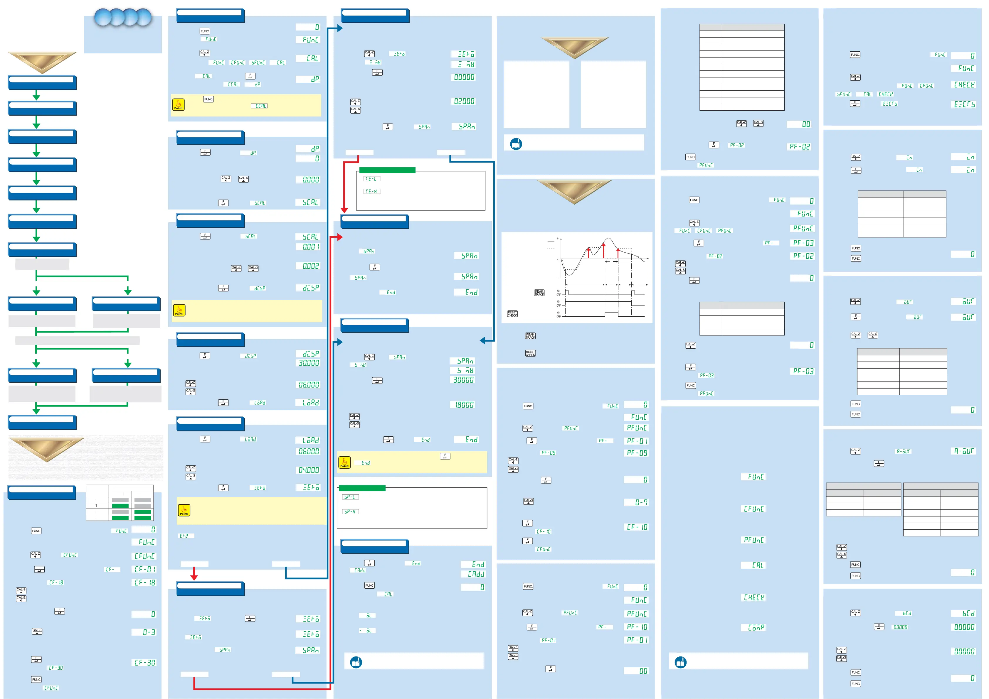
Selecting Calibration Number
Switching to Calibration Mode
Set of Decimal Point Position
Set of Minimum Scale
Set of Rated Capacity
Set of Actual Load
Zero Calibration (Actual Load)
Zero Calibration (Numerical Input)
Input a power of 100 VAC to 240 VAC and frequency of
50/60 Hz (or 12 VDC to 24 VDC) and energize CSD-709 for
ten minutes or so to stabilize CSD-709 and measuring part
(load cell).
CSD-709 can retain four patterns of calibration result.
Select a calibration number to calibrate.
Switch from measurement mode to calibration mode.
Set the decimal point display position.
Setting range: [0 (None)], [0.0], [0.00], [0.000], and [0.0000]
Set the minimum scale (minimum unit for measurement).
Setting range: [1], [2], [5], and [10]
Set the rated capacity (maximum load that can be
measured).
Set the load actually applied in span calibration.
To minimize calibration error, use a load at least two-thirds
of the rated capacity.
If a load cannot be applied, input the same value as the rated
capacity.
Is it possible to create no-load state
(initial state)?
Yes No
Yes No
(7) (7)
Read a load cell output value in no-load state
and register a zero point.
When no-load state (initial state) cannot be created,
register the output [mV/V] equivalent to no-load
state by numerical input.
Is it possible to apply a load two-thirds or more of the rated capacity?
(8) (8)
Span Calibration (Actual Load)
Span Calibration (Numerical Input)
Read a load cell output value while the load set
according to (6) Set of Actual Load is applied
and register a span point.
Register a span point [mV/V] obtained by subtracting the output
[mV/V] equivalent to no-load state from the output [mV/V] equivalent
to the load equal to the rated capacity by numerical input.
(9)
End of Calibration
Exit the calibration mode.
Calibration with actual load assumes
Calibration with actual load assumes a rated capacity
of 6.000 kg in the state where a load of 4 kg can be
applied and a minimum scale of 0.002 kg.
Calibration with numerical input assumes
Calibration with numerical input assumes 0.2 mV/V as
the output equivalent to no-load state (initial state) and
2 mV/V as the output equivalent to the rated capacity.
This unit can retain calibration results using four
calibration numbers: 0 to 3.
The LED ON/OFF state at the status display
indicates the current calibration number.
Yes No
(8)
Span Calibration (Actual Load)
(8)
Span Calibration (Numerical Input)
(9)
End of Calibration
- Peak hold
- Bottom hold
- Peak/bottom hold
- Peak-to-peak hold
- Maximum value hold
- Minimum value hold
- Maximum-minimum difference hold
- Average value hold
- 4-inflection points hold
- All zones
- Specified zone
- Time specified zone
- Automatic start time specified zone
Detection operation: Peak hold (hold a detected maximum load)
Detection zone: All zones The following describes the case using above conditions.
(1) Selecting Detection Condition Number
(1) Selecting Detection Condition Number
(3) Setting Detection Zone
(3) Setting Detection Zone
● Checking External Control Input
● Checking External Control Input
● Checking External Control Output
● Checking External Control Output
● Checking Analog Output
● Checking BCD Output
(2) Setting Detection Operation
(2) Setting Detection Operation
http://www.minebea-mcd.com/en/
product/i-amp/csd709.html
http://www.minebea-mcd.com/en/
product/i-amp/csd709.html
* As an example,
[00] is selected to set the detection operation to peak hold.
This unit allows the user to check various items via check mode.
(6) Press the [***] key and
select the number corresponding to desired detection zone
* As an example, [0] is selected to set the detection zone to all zones.
* To prevent the zero point from exceeding the adjustment range,
check the rated capacity of load cell, initial state, etc.
This blinks for about two seconds when the load cell output exceeds
the zero adjustment range of negative side(-2.5 mV/V or less).
This blinks for about two seconds when the load cell output exceeds
the zero adjustment range of positive side(2.5 mV/V or more).
Zero calibration error display
Yes No
Yes No
http://www.minebea-mcd.com/en/
product/i-amp/csd709.html
For detailed information,
refer to the instruction manual which can be found on our website.
Reference
(2) When the [***] key is pressed after displaying, [xxx] blinks and
the LED corresponding to the external control input turns on.
(3) Press the [***] key to display [xxx] .
(2) Press the [***] key four times.
The display changes in the following order: [xxx] -> [xxx] ->
[xxx] -> [xxx] -> [xxx] .
(1) Press the [***] key in the normal measurement mode to display [xxx] .
(4) Change the display to [xxx] .
: Select a digit to change.
: Change the value of the selected digit.
(3) Pressing the [***] key displays a two-digit number following [xxx] .
(2) Press the [***] key twice. The display changes in the following order:
[xxx] -> [xxx] -> [xxx] .
(8) Press the [***] key twice to return to the measurement mode.
The display shows [xxx] and then the measurement mode returns.
(7) Press the [***] key to confirm the detection condition number.
The display shows [xxx] .
(6) Press the [***] key to select a detection condition number you want to save.
A calibration number changes in the following order: [0] -> [1] -> [2] ... [7].
(5) After setting, press the [***] key.
The current detection condition number (0 to 7) will be displayed.
(4) Change the display to [xxx] .
: Select a digit to change.
: Change the value of the selected digit.
(3) Pressing the [***] key displays a two-digit number following [xxx] .
(2) Press the [***] key twice to display [xxx] .
(1) Press the [***] key in the normal measurement mode to display [xxx] .
(2) Press the [***] key twice to return to the measurement mode.
The display shows [CAL] and then the measurement mode returns.
(4) After setting, press the [***] key to display [End] .
(2) Then press the [***] key to display the stored load cell output
value.
(1) Press the [***] key while [xxx] is displayed to display
[ .
(3) Set a value obtained by subtracting the output value equivalent
to the zero point of load cell from the load cell output
value equivalent to the set rated capacity in mV/V.
: Select a digit to change.
: Change the value of the selected digit.
(3) When reading ends, [xxx] appears.
(2) [xxx] starts blinking and reading starts.
(1) While [xxx] is displayed,
apply the load set according to (6) Setting Actual Load
and press the [***] key
(4) After setting, press the [***] key to display [xxx] .
(3) Set the output value equivalent to no-load state in mV/V.
: Select a digit to change.
: Change the value of the selected digit.
(1) Press the [***] key while [Zero] is displayed
to display [xxx] .
(3) When reading ends, [xxx] appears.
(2) [xxx] starts blinking and reading starts.
(1) While [xxx] is displayed, press the [***] key
without applying a load.
Error display in rated capacity/actual load setting
This blinks for about two seconds when you set a value meeting [Rated capacity] < [Actual load].
* Correct settings so that “Rated capacity ≥ Actual load” is met.
(2) Set the actual load value.
: Select a digit to change.
: Change the value of the selected digit.
(1) When the [***] key is pressed while [xxx] is displayed,
the currently stored actual load is displayed.
(3) After setting, press the [***] key to display [xxx] .
(2) Set the rated capacity.
: Select a digit to change.
: Change the value of the selected digit.
(2) Set the minimum scale.
Select the minimum scale using [***] and [***] keys.
The last two digits change as follows: [01], [02], [05], and [10].
(1) When the [***] key is pressed while [xxx] is displayed,
the currently stored minimum scale is displayed.
(2) Set the position of decimal point.
Select the position using [***] and [***] keys.
The position of decimal point can be selected from [0 (None)], [0.0], [0.00],
[0.000], and [0.0000].
(1) When the [***] key is pressed while [xxx] is displayed,
a decimal point is displayed at the currently stored position.
(2) Press the [***] key three times. The display changes in the
following order: [xxx] -> [xxx] -> [xxx] -> [xxx] .
(7) Press the [***] key to confirm the calibration number.
The display becomes [xxx] .
(2) Press the [***] key to display [xxx] .
(3) Pressing the [***] key displays a two-digit number following [xxx] .
(2) Press the [***] key twice to display [xxx] .
Select an item to check from the following items and take the procedure.
ON: Detects and displays a peak value. (Detection zone (1))
OFF: Displays the current load. (Load display zone)
Used to check the following items.
- Comparison value setting contents
- Setting contents related to the comparator, etc.
COMP selection mode
External control input LED name
INPUT1 turns ON
INPUT2 turns ON
INPUT3 turns ON
INPUT4 turns ON
INPUT5 turns ON
INPUT6 turns ON
SEL1
SEL2
CHECK
HOLD
PEAK
MEAS.
External control outputLED name
OUT1
OUT2
OUT3
OUT4
SEL1
SEL2
OUTPUT1 turns ON
OUTPUT2 turns ON
OUTPUT3 turns ON
OUTPUT4 turns ON
OUTPUT5 turns ON
OUTPUT6 turns ON
Current output card
DisplayOutput value
4 mA
12 mA
20 mA
LOW
MID
HI
Voltage output card
DisplayOutput value
0 V
5 V
10 V
0 V
-5 V
-10 V
LOW
MID
HI
-LOW
-MID
-HI
Blinks
Blinks
(Measurement mode)
(Measurement mode)
(Measurement mode)
Blinks
Calibration
Procedure
Calibration
Procedure
Calibration
Procedure
Energizing power supply
Advanced preparation
Selecting Calibration Number
(1)
(1) Press the [***] key in the normal measurement mode to display [xxx] .
(Measurement mode)
Proceed to step
(2)
(2)
Switching to Calibration Mode
(3)
Setting Decimal Point Position
(4)
Setting Minimum Scale
(5)
Setting Rated Capacity
(6)
Setting Actual Load
(7)
Zero Calibration (Actual Load)
(1) Press the [***] key in the normal measurement mode
to display [xxx] .
(Measurement mode)
(3) When [CAL] is displayed, press the [***] key twice.
The display changes from [xxx] to [xxx] .
■
When the [***] key is pressed after taking the steps in (2) Switching to Calibration Mode,
the previous set value will be canceled and [xxx] will return on the display.
When you cancel the process halfway, the set value will not be saved.
Stored position
Set position
(3) After setting, press the [***] key to display [xx] .
Stored position
Set position
(3) After setting, press the [***] key to display [xxx] .
Example of display change caused by minimum scale setting
■
With the minimum scale set to [02], the load display changes as follows: [0.002] -> [0.004]
-> [0.006] (decimal point set to [0.000]).
(1) When the [***] key is pressed while [xxx] is displayed,
the currently stored rated capacity is displayed.
Stored rated capacity
Set rated capacity
Stored actual load
Set actual load
kg
kg
kg
kg
(3) After setting, press the [***] key to display [xxx] .
■
Set the actual load value used for calibration to a value at least two-thirds of the rated capacity.
■
When the load which is the same as the rated capacity can be applied, set the actual load
equal to the rated capacity.
■
When span calibration is performed with numerical input according to (8) Span Calibration
(Numerical Input), set the actual load equal to the rated capacity.
Proceed to zero calibration.
Is it possible to create no-load state (initial state)?
Read a load cell output value in no-load state (initial state) and
register a zero point.
Blinks
Proceed to span calibration.
Is it possible to apply a load two-thirds or more of the rated capacity?
(7)
Zero Calibration (Numerical Input)
Proceed to
(9)
(Measurement mode)
Only when CSD-709 in use is replaced with another CSD-709 and also
all the following conditions are met, zero calibration is performed with numerical input.
- Zero calibration data (mV/V value) obtained before replacement remains.
- No-load state (initial state) cannot be created.
(2) Then press the [***] key to display the stored load cell output value.
Stored load cell output value
Set load cell output value
mV/V
mV/V
Proceed to span calibration.
Is it possible to apply a load two-thirds or more of the rated capacity?
Read a load cell output value while the actual load set according to
(6) Setting Actual Load is applied and register a span point.
Blinks
■
A set value remains in provisionally-registered state until the [***] key is pressed with
[xxx] displayed to confirm the value. When you cancel the process halfway,
the set value will not be saved.
Register a span point by inputting a value obtained by subtracting the load cell output value at
the zero point from the load cell output value expected when the load equal to the rated
capacity is applied.
Stored load cell output value
Set load cell output value
mV/V
mV/V
(1) When the [***] key is pressed while [End] is displayed,
[xxx] appears and the set data is stored in the internal memory.
Measurement error display
* To display an overload error, any of the following conditions can be set.
When the load display
- falls below “(- Rated capacity) - 9 divisions”
- falls below “-110 % of rated capacity”
- falls below “-20 divisions”
When the load display
- exceeds “(+ Rated capacity) + 9 divisions”
- exceeds “+110 % of rated capacity”
Detection Types
Detailed Detection Procedure
Detailed Detection Procedure
Detection operation Detection zone
Actual load
Displayed value
Detection zone (1)
Time
Detection
zone (2)
RESET
zone
Load
display
zone
key
During peak detection
This unit can retain up to eight detection conditions using the detection condition numbers 0 to 7.
The following describes the setting procedure.
(Measurement mode)
Stored detection
condition number
Set detection
condition number
(1) Press the [***] key in the normal measurement mode to display [xxx] .
(Measurement mode)
* To prevent the span point from exceeding the adjustment range,
check the rated capacity of load cell, actual load, etc.
This blinks for about two seconds when the load cell output exceeds the span
adjustment range(larger than 3.1 mV/V).
This blinks for about two seconds when the load cell output falls short of the span
adjustment range(Load cell output voltage at span point - Load cell output voltage at
zero point ≤ 0.0 mV/V).
Span calibration error display
key or RESET input
ON: Displays 0. (RESET zone)
OFF: Resumes peak value detection. (Detection zone (2))
Detection operationNo.
00
01
02
03
04
05
06
07
08
09
10
11
Peak
Bottom
Peak/bottom
Peak-to-peak
Minimum value
Maximum value
Maximum-minimum difference
Inflection point A
Inflection point B
Inflection point C
Inflection point D
Average value
Detection operation numbers and corresponding detection operations
Detection zone numbers and corresponding detection zones
(Measurement mode)
Detection zoneNo.
0
1
2
3
All zones
Specified zone
Time specified zone
Automatic start time specified zone
The following modes are used to perform measurement or operate CSD-709.
Displays the current measurement value. The measurement mode is divided into two modes.
- Tracking mode: Displays an input value from measuring instrument which varies with time.
- Peak mode: Detects and retains a maximum/minimum point, etc. in measurement values.
Measurement mode
Allows the user to set the following functions or check the setting contents.
- Measurement function (AD sampling count, digital filter, etc.)
- Comparison function (comparator operation, etc.)
- Operation function (key lock, hold target, etc.)
Function mode
Allows the user to set the following functions or check the setting contents.
- Calibration number selection
- Decimal point display position
- Current calibration data, etc.
C function mode
Allows the user to set the following functions or check the setting contents.
- Detection zone
- Detection operation, etc.
P function mode
This mode is divided into the following four modes.
- CCAL mode: Calibration
- CADJ mode: Fine adjustment of calibration results
- VCAL/VADJ mode: Calibration or adjustment for options such as current/voltage output card
CAL selection mode
Used to check the following items.
- ROM version of CSD-709
- Mounted options
- Externally controlled operation, etc.
CHECK mode
(Measurement mode)
Switching to Check Mode
(1) Press the [***] key in the normal measurement mode to display [xxx] .
(5) Press the [***] key.
The current detection zone number will be displayed.
Stored detection
zone number
PEAK/TRACK input
0
Detailed
Calibration
Procedure
Detailed
Calibration
Procedure
(3) Pressing the [***] key displays a two-digit number following [xxx] .
(4) Change the display to [xxx] .
: Select a digit to change.
: Change the value of the selected digit.
(5) After displaying, press the [***] key.
The current calibration number (0 to 3) appears.
Set calibration number
(6) Press the [***] key to select a calibration number with which you want to
save the calibration result. A calibration number changes
in the following order: [0] -> [1] -> [2] -> [3].
(8) Press the [***] key twice to return to the measurement mode.
The display shows [xxx] and then it returns to the measurement mode.
Calibration
Procedure
Detection Procedure Detection Procedure Detection Procedure Detection Procedure
Detection Procedure
Check Mode Check Mode Check Mode Check Mode
Check Mode
(4) Change the display to [xxx] .
: Select a digit to change.
: Change the value of the selected digit.
(5) After displaying, press the [***] key.
The current detection operation number will be displayed.
Stored detection
operation number
Modes
 Loading...