http://mini-box.com, Embedded PC Solutions
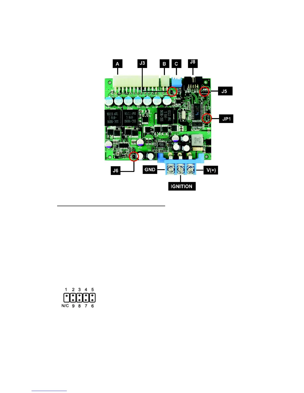
1.2 M4-ATX Connection diagram
Power Input Connectors (bottom, right side)
Left Battery negative (GND)
Center Ignition (switched battery, positive. Can test by connecting it to Battery +)
Right Battery positive (+)
(A) ATX Power Output Connector 20/24 pin connector
(B) 12V-ATX power output connector 4 pin
(C) Configuration dip switch
(J5) For internal use only (do not use)
(J6) Amplifier THUMP wire harness (connects to the M4-ATX pin header)
(J3) Fan Header
(J8) USB, Motherboard ON/OFF and THUMP (Thump also available on J6)
1) +5V 6) To Motherboard ON/OFF
2) USB D- 7) To motherboard ON/OFF
3) USB D+ 8) Amplifier Thump
4) GND 9) GND
5) GND 19 N/C (key)
M4-ATX User Guide Page 2