EasyManua.ls Logo

Mirage B 1018 G User Manual

Mirage B 1018 G
16 pages
To Next Page IconTo Next Page
Page #1 background imageLoading...
Page #1 background image
1
Mirage B 1018 G
This compact, rugged, VHF RF power amplifier greatly improves signal-quality and
range. This unit contains a low-noise GAsFET receiving amplifier, a 160-watt power
amplifier, and associated control and protection circuitry.
This amplifier operates from any well-filtered direct-current 11-15 volt power source
capable of supplying 30 amperes under full-load. The power source must be either
negative grounded or totally ground independent.
Warning, never use this unit with:
1.) positive-ground supplies
2.) vehicles having positive-ground batteries
3.) power sources exceeding 16 volts
Always fuse power leads at the battery with 30-ampere fast-blow fuses.
This amplifier has the following important features:
1.) Automatic RF actuated transmit and receive switching or manual switching
2.) Active bias for greatly improved SSB linearity
3.) Low-noise GAsFET receive preamplifier
4.) True push-pull circuitry and clean RF layout for excellent stability
5.) Excess SWR and overdrive protection
6.) Remote control capabilities

Other manuals for Mirage B 1018 G

Question and Answer IconNeed help?

Do you have a question about the Mirage B 1018 G and is the answer not in the manual?

Mirage B 1018 G Specifications

General IconGeneral
BrandMirage
ModelB 1018 G
CategoryAmplifier
LanguageEnglish

Summary

1.0 Mounting Considerations

1.2 Power Wiring

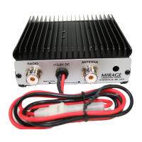
Details correct power lead connection, fusing requirements, and voltage specifications for safe operation.

1.4 Mobile Mounting Considerations

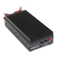
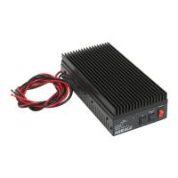
Provides guidance on selecting optimal locations and mounting the amplifier within a vehicle.

2.0 Radio or Exciter

2.1 Drive Level

Defines recommended input power levels for driving the amplifier to prevent damage and ensure linearity.

3.0 FM, CW and Non-Linear Modes

3.1 Drive Power

Specifies drive power limits for FM, CW, FSK modes and warns about meter accuracy.

4.0 SSB and Linear Modes

4.1 Splatter and Distortion

Explains linearity issues like splatter and distortion and how active bias helps minimize them.

4.2 Drive Power

How to set drive power for SSB/AM using peak-reading meters or oscilloscopes for optimal linearity.

4.5 Power Output

Specifies maximum linear SSB output power and requirements for the power source for best linearity.

6.0 In Case of Difficulty

6.1 Does Not Transmit or Receive at All

Troubleshooting steps for complete failure of transmit or receive functions.

8.0 Schematic