MISTRAL MAX
2
CAR ALARM WITH HOPPING CODE • INSTALLATION MANUAL 2/2
SK
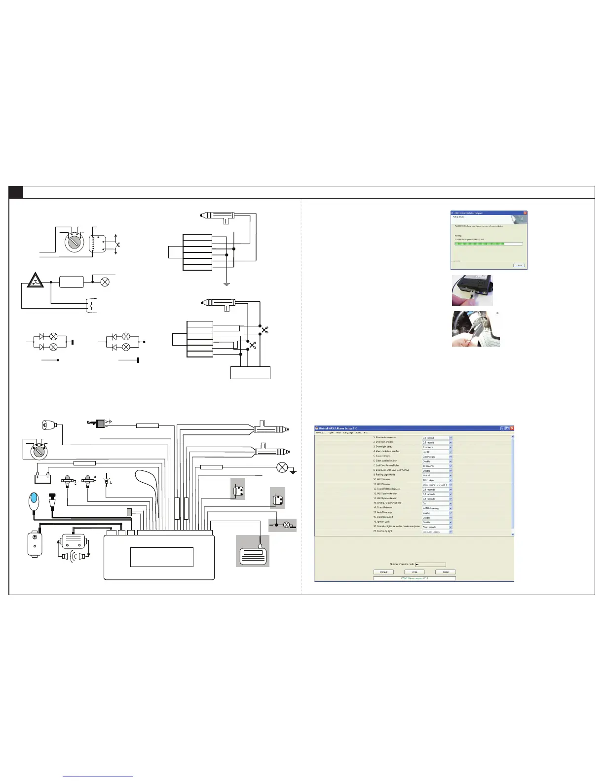
Example of wiring diagram for door locking system
EXAMPLE OF WIRING DIAGRAM
X. PROGRAMMING CAR ALARM VIA PC
The car alarm MISTRAL MAX
2
is possible to program via PC, too. To connect car alarm with PC and
set parameters via PC, you need MISTRAL PROG programming cable and MISTRAL MAX
2
Alarm setup
application, which must be installed before alarm connection. After installation of MISTRAL PROG cable
and MAXprog application software is everything ready for programming.
Postup inštalácie ovládacieho súbora pre programovací kábel
After unzipping archive file Cable_PL-2303_Drivers.zip, you must run the file PL2303_Prolific_
WDMDriverInstaller_v1.6.1.exe, from unzipped folder.
- The program starts and displays the information page. It is possible to click Next.
- Files needed for a programming cable begin to install.
- After files successfully installed, installation complete page shows.
MISTRAL MAX
2
programming process
- Plug in connector of programming cable to the alarm.
- Alarm must be powered through the red (+) and black (ground).
- Connect the USB connector into a free USB port.
- Run MAXprog.exe. Program version can be updated, by adding alarm options. Watch distributor
web site.
- Alarm login to the program will be automatically (green text of alarm firmware version will display in
the row).
For reading configuration from the car alarm you need click on to Read button firstly.
Application function description
Save as.. - click on if you want actually configuration data from the display to write into file on the PC.
Open - click on if you want load configuration data from file into application. Loaded values are
immediately showed on the display.
Print - actually configuration values from display is printed on the printer.
Language - it is possible to select application language.
Exit - application ended.
Read - click on if you want to receive configuration from car alarm into the PC. Received values are
immediately showed on the display.
Write - click on if you want to send actually configuration from the display to car alarm.
Default - click on if you want to set car alarm to factory settings.
Number of service code - it is possible to set code for emergency disarming. For writing this
emergency code into the car alarm, you need click on to Write button..
EN
 Loading...