Do you have a question about the Mitsubishi Electric 9900B Series and is the answer not in the manual?
| Model | 9900B Series |
|---|---|
| Category | UPS |
| Frequency | 60 Hz |
| Topology | Double Conversion |
| Communication Interface | Ethernet |
Explains warning, caution, and note icons used in the manual for safety.
Essential safety guidelines for installation and maintenance of the UPS and batteries.
Highlights lethal voltages and consequences of unauthorized modifications.
Steps for applying the UPS to equipment affecting human safety, requiring consultation.
Details the required environmental conditions for UPS installation and operation.
Specifies the recommended bypass input circuit breaker (MCCB) for system protection.
Provides an overview of the UPS capabilities, models, and manual content.
Defines key terms and components related to the Uninterruptible Power Supply System.
Describes the UPS operation where the inverter supplies power to the critical load.
Explains operation where the load is supplied via the internal static bypass line.
Details UPS operation powered by the battery during AC input failure.
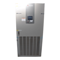
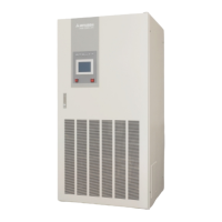
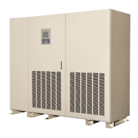
Diagrams showing component locations in UPS cabinet and modules for different kVA models.
Details the Display PCB, External I/F PCB, and Parallel I/F PCB with switch functions.
Identifies the Main PCB UPGR-M and its associated switches for service personnel.
Describes the functions of various operational and service switches.
Details rated output, input, and bypass voltages for different UPS capacities.
Provides physical dimensions, weight, and heat rejection for UPS modules.
Lists detailed performance parameters for AC input, battery, AC output, and environment.
Specifies the ratings for contactors, breakers, and fuses used in the UPS system.
Explains the meaning and color of various LEDs on the UPS front panel.
Details the Emergency Power Off (EPO) button and its function to shut down the UPS.
Describes the LCD panel's functions, main menu, and startup/shutdown guidance.
Covers the Measurement menu for input/output values and Operation menu for settings.
Explains how to access and view event logs and battery operation logs.
Shows what appears on the LCD during an input power failure and battery operation.
Details how faults and alarms are displayed and how to silence audible alarms.
Describes the layout and function of output terminals for external alarm annunciation.
Explains the function of input terminals for remote UPS control and monitoring.
Details the Form 'A' dry type output contacts for external alarm annunciation.
Lists selectable output and input contact features for alarms and remote access.
Provides wiring configuration for remote start/stop, EPO, and other input functions.
Lists selectable input contact items and their default assignments for remote access.
Information on external communication methods using Lookups.
Covers safe transportation, installation, environmental, and space requirements.
Instructions for connecting wires, recommended cable sizes, torque, and hardware.
Diagrams and procedures for parallel connection of multiple UPS units.
Guides for safely starting up, shutting down, and operating the UPS in bypass mode.
Procedures for Multi Module System (MMS) startup and operation modes.
Outlines the steps to take when a UPS fault occurs, including silencing alarms and contacting support.
Details when to replace the UPS battery based on its lifespan and capacity.
Recommends contacting service for UPS component life expectancy and replacement schedules.
Describes how to identify and record fault codes for troubleshooting and service.
Lists fault codes UA801-UA821, their meanings, guidance, and relay contact status.
Lists fault codes UA822-UF056, covering breaker status, battery issues, and converter faults.
Lists fault codes UF103-UF203, detailing DC faults, overcurrent, and inverter voltage issues.
Lists fault codes UF204-UF230, covering output errors, control circuit issues, and fan faults.
Lists fault codes UF253-UF452, detailing output voltage, load, synchronization, and contactor errors.
Explains the meaning of code prefixes (UA, UF, U%) and numeric indicators.
Details warranty provisions for direct purchases and reseller purchases.
Instructions for updating product registration for prompt support and warranty access.
Lists available service offerings including maintenance, warranty, and site evaluation.
Describes various service packages and their included features like site visits and maintenance.