EasyManua.ls Logo

Mitsubishi Electric City Multi PEFY-P140VMH-E User Manual

Mitsubishi Electric City Multi PEFY-P140VMH-E
31 pages
To Next Page IconTo Next Page
Page #1 background imageLoading...
Page #1 background image
TECHNICAL & SERVICE MANUAL
Air-Conditioners For Building Application
<Indoor unit>
2004
Models
Ceiling Concealed
Series PEFY
PEFY-P40VMH-E,PEFY-P50VMH-E
PEFY-P63VMH-E,PEFY-P71VMH-E
PEFY-P80VMH-E,PEFY-P100VMH-E
PEFY-P125VMH-E,PEFY-P140VMH-E
PEFY-P200VMH-E,PEFY-P250VMH-E
INDOOR UNIT
CONTENTS
SAFETY PRECAUTIONS ·························1
1. FEATURES ···········································3
2. PART NAMES AND FUNCTIONS ········4
3. SPECIFICATION ···································6
4. OUTLINES AND DIMENSIONS············9
5. WIRING DIAGRAM ·····························11
6.
REFRIGERANT SYSTEM DIAGRAM
13····
7. TROUBLE SHOOTING·······················14
8. DISASSEMBLY PROCEDURE···········
17
For use with the R410A & R407C & R22
Question and Answer IconNeed help?

Do you have a question about the Mitsubishi Electric City Multi PEFY-P140VMH-E and is the answer not in the manual?

Mitsubishi Electric City Multi PEFY-P140VMH-E Specifications

General IconGeneral
BrandMitsubishi Electric
ModelCity Multi PEFY-P140VMH-E
CategoryAir Conditioner
LanguageEnglish

Summary

Safety Precautions

General Safety Precautions

Important safety guidelines for installation and operation.

Refrigerant Handling Precautions

Specific safety measures for R410A and R407C refrigerant systems.

Product Features

Model and Capacity Overview

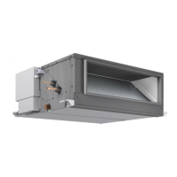
Overview of available models and their cooling/heating capacities.

Technical Specifications

Unit Specifications

Detailed technical specifications for the air conditioning units.

Electrical Component Specifications

Specifications for electrical components and parts.

Installation Dimensions

Dimensions for PEFY-P40-140 Models

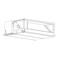
Physical dimensions and installation space requirements for specific models.

Dimensions for PEFY-P200-250 Models

Physical dimensions and installation space requirements for larger models.

Diagrams and Schematics

Wiring Diagram for PEFY-P40-140 Models

Electrical wiring schematic for specific indoor unit models.

Wiring Diagram for PEFY-P200-250 Models

Electrical wiring schematic for larger indoor unit models.

Refrigerant System Diagram

Diagram illustrating the refrigerant circuit and key components.

Troubleshooting and Settings

Component Checking Procedures

Procedures for checking the functionality of various unit components.

Address Switch Settings

Instructions for setting the unit's address using rotary switches.

Default Dip-Switch Configuration

Default dip-switch settings for different models upon delivery.

Test Run Procedures

Important considerations for performing a test run of the unit.

Service Board LED Functions

Explanation of the function of LEDs on the indoor unit service board.

Disassembly Procedures

Control Box Disassembly

Step-by-step guide to disassembling the control box.

Fan and Fan Motor Removal

Procedure for removing and servicing the fan and fan motor.

LEV and Thermistor Removal

Steps for removing the LEV and thermistors.

Heat Exchanger Removal

Procedure for removing and replacing the heat exchanger.

Control Box Internal Layout

Diagram showing the internal layout of components within the control box.

Sensor Component Locations

Location of various sensors within the indoor unit.

Related product manuals