386
5. PARAMETERS
5.11 (A) Application parameters
Operation of the self power management function
• This function controls the magnetic contactor (MC) on the input side using the output relay to reduce the standby power
during inverter stop. With the terminals R1/L11 and S1/L21 (refer to page 60) and 24 V external power supply input (refer
to page 63), the main circuit power supply and control circuit power supply are separated, and the MC for main circuit power
supply is controlled by the electronic bypass MC1 signal.
•Set Pr.248 Self power management selection = "1 or 2", Pr.30 Regenerative function selection "20, 21, 120, or 121"
(other than DC feeding mode 2), and Pr.190 to Pr.196 (Output terminal function selection) = "17 (positive logic)" to
assign the Electronic bypass MC1 (MC1) signal to an output terminal.
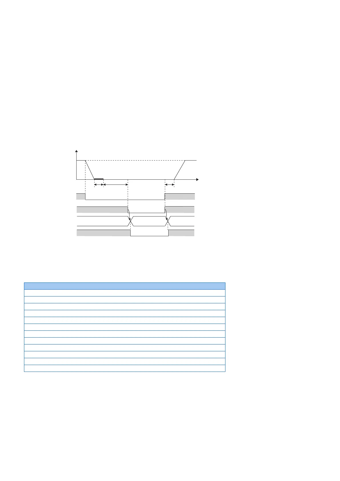
• After the inverter is stopped and the time set in Pr.11 DC injection brake operation time and Pr.254 Main circuit power
OFF waiting time have passed, turning OFF the MC1 signal releases the MC on the input side (main circuit power supply
OFF). Set Pr.254 to prevent frequent MC operation.
• Turning ON the start signal turns ON the MC1 signal and closes the MC on the input side (main circuit power supply ON).
After the time set in Pr.137 Start waiting time has passed, the inverter starts. Set time slightly longer (about 0.3 to 0.5 s)
than the time period from the MC1-ON to the actual pick-up operation of the MC is turned ON in Pr.137.
• When the protective function of the inverter is activated, the MC1 signal is immediately turned OFF according to the Pr.248
setting. (The MC1 signal is turned OFF before the time set in Pr.254 has passed.) When Pr.248="1", the MC1 signal is
turned OFF when the protective function is activated due to any cause. When Pr.248="2", the MC1 signal is turned OFF
only when the protective function is activated due to an error resulted from a failure in the inverter circuit or a wiring error
(refer to the following table). (For the alarm details, refer to page 570.)
Fault record
Inrush current limit circuit fault (E.IOH)
CPU fault (E.CPU)
CPU fault (E.6)
CPU fault (E.7)
Parameter storage device fault (control circuit board) (E.PE)
Parameter storage device fault (main circuit board) (E.PE2)
24 VDC power fault (E.P24)
Operation panel power supply short circuit/RS-485 terminals power supply short circuit (E.CTE)
Output side earth (ground) fault overcurrent (E.GF)
Output phase loss (E.LF)
Internal circuit fault (E.BE)
Internal circuit fault (E.13/E.PBT)
STF
ON
MC1
ON
Time
DC brake
Pr.11 Pr.254
Output frequency
(Hz)
ON
ON
Main circuit power supply
ON
ON
Power supply mode RST input RST input
R1S1 input/
external 24 V input
OFF
OFF
OFF
Pr.137
 Loading...


