EasyManua.ls Logo

Mitsubishi Electric FX Series - Layout of the MELSEC FX1 N Base Units; Layout of the MELSEC FX2 N Base Units

Mitsubishi Electric FX Series
284 pages
To Next Page IconTo Next Page
To Previous Page IconTo Previous Page
Loading...
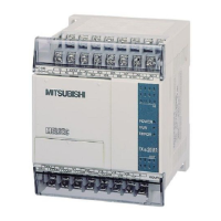
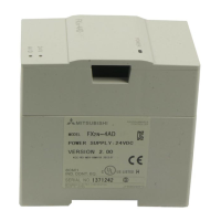
2.6.3 Layout of the MELSEC FX1N base units
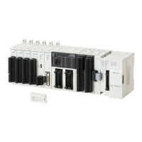
2.6.4 Layout of the MELSEC FX
2N base units
Controller Design The Hardware
2-10 MITSUBISHI ELECTRIC
Memory battery
Terminals for
digital inputs
Removable terminal
strip for digital outputs
Connection for
extensions
LEDs for indicating
the output status
Protective cover for
expansion bus
Housing cover
Connection for
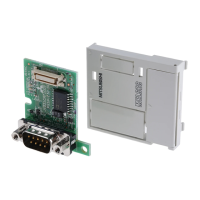
expansion adapter boards
Connection for
programming units
LEDs for indicating
the operating status
RUN/STOP switch
LEDs for indicating
the input status
Slot for memory
cassettes
Connection for the
ser vice power supply
Mounting hole
Terminal cover
Protective cover
Protective cover
Terminals for
digital outputs
Connection for the
ser vice power supply
Connection for
programming units
Mounting hole
Terminal cover
RUN/STOP switch
Slot for memory cassettes,
adapters and displays
2analog
potentiometers
0123
4567
8 9 10 11
12 13 14 15
0123
4567
10 11
IN
OUT
POWER
FX -24MR
1N
RUN
ERROR
100-240
VAC
X7
X11
X13
X15
X5
X3
X1
S/S
X6
X10
X12
X14
X4
X2
X0
N
L
24MR
-ES/UL
Y10
Y6
Y5
Y3
COM3
Y4
COM4
Y7
Y11
COM2
COM1
COM0
24+
Y2
Y1
Y0
0V
MITSUBISHI
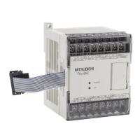
Extension bus
Connection of the
power supply
LEDs for indicating
the operating status
LEDs for indicating
the input status
Protective cover
Lid
Terminals for
digital inputs
LEDs for indicating
the output status
Housing cover

Table of Contents

Related product manuals