2.6.5 Layout of the MELSEC FX2NC base units
2.6.6 Layout of the MELSEC FX
3G base units
The Hardware Controller Design
Training Manual GX IEC Developer 2 - 11
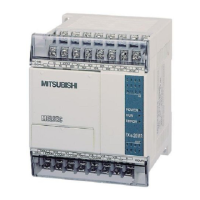
Terminals for
digital outputs
Terminals for
digital inputs
Memory cassette slot
Memory cassette
(optional)
Cover
RUN/STOP switch
Extension bus
(on side)
Battery
compartment
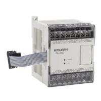
LEDs for indicating
the output status
Protective cover
for expansion bus
Operating status LEDs
2nd interface
for CNV adapter
Memory battery
LEDs for indicating
the input status
Connector for
terminal strips
Protective cover
POWER
RUN
BATT
ERROR
X0
1
2
3
X4
5
6
7
Y0
1
2
3
Y4
5
6
7
RUN
STOP
MITSUBISHI
FX -16MR-T-DS
2
N
C
MELSEC
COM
X7
X6
X5
X4
•
COM
X3
X2
X1
X0
Y4
•
COM1
Y3
Y2
Y1
Y0
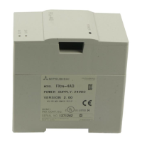
Connectors für memory
cassette, display mod ule,
and expansion board
Option battery holder
Flip cover for programming
port, potentiometer and
Run/Stop switch
Cover for the lef t expansion
connector
2 analog potentiometers
RUN/STOP switch
Protective cover
Expansion bus
connector cover
Protective cover
LEDs for indicating
the output status
Cover for the right expansion
connector and the optional
battery
Input indicator LEDs
Input terminals
Terminal cover
Operation status
indicator LEDs
Input terminals
Terminal cover
Programming por t: RS-422
Programming por t: USB

 Loading...