1 Introduction
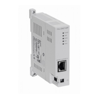
1.3 Status LEDs
14
FX3U-1PG User's Manual
1.3 Status LEDs
1.4 Terminal Layout
• Terminal block screw size and tightening torque
Terminal block screw: M3 screw
Tightening torque: 0.5 to 0.8 N•m
Do not tighten terminal block mounting screws with a torque outside the above-mentioned range. Failure to
do so may cause equipment failures or malfunctions.
LED
display
LED
color
Status Description
POWER Green
OFF 5 V DC is not being supplied from the PLC
ON 5 V DC is being supplied from the PLC
STOP Red
OFF STOP input OFF
ON STOP input ON
DOG Red
OFF DOG input OFF
ON DOG input ON
PG0 Red
OFF Zero point signal OFF
ON Zero point signal ON
FP Red
OFF Forward pulse or pulse train interrupted
Flicker Forward pulses or pulse train is being output
RP Red
OFF Reverse pulse or directional output interrupted
Flicker Reverse pulses is being output
ON Directional output is being output
CLR Red
OFF CLR signal is not output
ON CLR signal is being output
ERR Red
OFF Operating normally
Flicker Error occurred
ON CPU error occurred
Terminal name Description
VIN Power terminal for pulse output
COM0 Common terminal for pulse output
FP Terminal which outputs forward pulse or pulse train
RP Terminal which outputs reverse pulse or direction signal
PG0- Input terminal for zero point signal
PG0+ Power terminal for zero point signal
COM1 Common terminal for CLR signal output
CLR Terminal for CLR signal output
S/S 24 V DC power terminal for STOP input and DOG input
STOP Terminal for STOP input or interrupt input 1
DOG Terminal for DOG input or interrupt input 0
VIN
COM0
RP
PG0+
PG0-
FP
COM1
CLR
STOP
DOG
S/SS/S
 Loading...