Do you have a question about the Mitsubishi Electric Lossnay VL-250CZPVU-L-E and is the answer not in the manual?
| Model | VL-250CZPVU-L-E |
|---|---|
| Category | Fan |
| Manufacturer | Mitsubishi Electric |
| Airflow Rate | 250 m³/h |
| Airflow Rate (Low) | 125 m³/h |
| Airflow Rate (High) | 250 m³/h |
| Power Supply | AC |
| Voltage | 220-240 V |
| Frequency | 50/60 Hz |
| Application | Residential, Commercial |
| Sound Level (Low) | 25 dB(A) |
| Operating Temperature Range | -10°C to +40°C |
Details specific hazards like electric shock, modification prohibition, and risks of injury or property damage.
Emphasizes earth condition checks, power supply isolator, and overload protection for safe servicing.
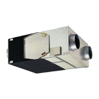
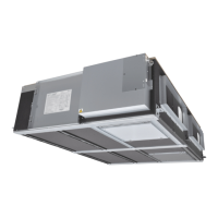
Identifies key components like filters, heat exchanger, and controller with their functions.
Lists optional filters, their models, materials, and replacement intervals.
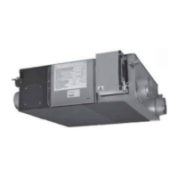
Details model, materials, dimensions, weight, electrical supply, and performance data.
Illustrates external dimensions and mounting details for the VL-250CZPVU-L-E model.
Specifies clearances needed around the unit for installation and maintenance access.
Presents wiring diagrams for various models, including wiring examples and symbol definitions.
Diagram of the control circuit board showing component locations and connection points.
Diagram of the power circuit board, identifying connectors, fuses, and key components.
Diagram of the power interface circuit board, showing connections and component layout.
Diagram of the signal interface circuit board, showing connections for external devices.
Details terminal categories, input/output, ratings, and sensor/switch requirements.
Lists and describes available function settings, their values, and factory defaults.
Provides a service flowchart and preliminary checks to identify and resolve issues.
Checks power supply, cable connections, and indicator lights for failure mode 1.
Checks signal cable wiring, connections, and output capacity.
Ensures correct function selection switches and controller settings are applied.
Explains the meaning of LEDs on the circuit board for diagnosing faults.
Diagnoses issues where the controller is unresponsive or displays error codes.
Addresses problems with controller display, startup, or mode changes.
Lists error codes and LED blinking patterns to identify and resolve malfunctions.
Addresses condensation and identifies causes of abnormal noises from fans, motors, or dampers.
Checks for damper motor failure or adhesion issues, providing corrective actions.
Diagnoses issues with external devices connected via analog, contact, or serial signals.
Guides diagnosis of power circuit board and DC motor for failures due to voltage or lightning.
Details procedures for checking thermistor resistance and detecting failures.
Records basic unit information and function selection switch settings.
Documents controller-based function settings and external terminal usage.
Checklist for verifying correct installation, connections, and operational status before use.
Safety guidelines and precautions to follow before starting any disassembly or repair work.
Steps to safely turn off power and remove the heat exchanger assembly.
Instructions for removing the outer front casing, including screw locations and torque.
Steps to remove the inner front casing and filter case, with precautions for heavy parts.
Guidance on safely removing the heat exchanger, noting its weight and handling precautions.
Instructions for removing the PCB cover, including screw locations and torque specifications.
Guidance on removing lead wires and precautions to avoid damaging styrene components.
Steps for removing the upper PCB cover, including screw locations and assembly precautions.
Instructions for removing the lower PCB cover, showing circuit board locations within the control box.
Steps to remove thermistors (OA and RA), including fixing screws and torque.
Instructions for removing the damper assembly, including lowering the circuit board for access.
Procedure for removing the fan assembly, including disconnecting motor connectors and lead clips.
Steps to remove the control circuit board and power supply cord, with precautions for replacement.
Instructions for removing the control box, including disconnecting leads and screws.
Details on how to disconnect the power supply cord using a ratchet.
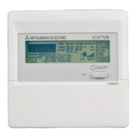
Steps to remove the controller, including opening the front cover and disconnecting connectors.
Guidance on correctly connecting thermistor and damper connectors inside the control box.
Instructions for routing controller and thermistor lead wires after installing PCB covers.
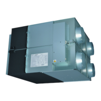
Steps to safely turn off power and remove the heat exchanger for VL-350 models.
Instructions for removing the outer front casing for VL-350 models, including screws and washers.
Steps for removing the reinforcement, with precautions against dropping the part.
Instructions for removing the inner front casing for VL-350 models by sliding it downwards.
Guidance on safely removing the heat exchanger for VL-350 models, noting its weight.
Steps for removing the PCB cover for VL-350 models, differentiating between L and R types.
Instructions for removing lead wires and the upper PCB cover for VL-350 models.
Steps for removing the upper PCB cover for VL-350 models, with assembly precautions.
Instructions for removing the lower PCB cover for VL-350 models.
Steps to remove the fan assembly, including lowering the circuit board for access.
Steps to remove the OA thermistor for VL-350 models, including connector and lead clamp removal.
Steps to remove the RA thermistor for VL-350 models, including connector and lead clamp removal.
Instructions for removing the damper assembly for VL-350 models, involving frame and lead removal.
Steps to remove circuit boards and power supply cords for VL-350 models.
Procedure for removing the controller for VL-350 models.
Guidance on reconnecting EA fan motor connectors and arranging controller cable wires.
Explains abbreviations used for different types of screws in the parts catalog.