2 - 72
REPLACEMENT OF MELSECNET (II) AND /B (PLC TO PLC NETWORK)
2
The following shows the replacement precautions when replacing MELSECNET (II) with MELSECNET/
H.
(1) Cables
For details on precautions for optical cables and coaxial cables, refer to Section 2.2.2 Cable
performance comparisons.
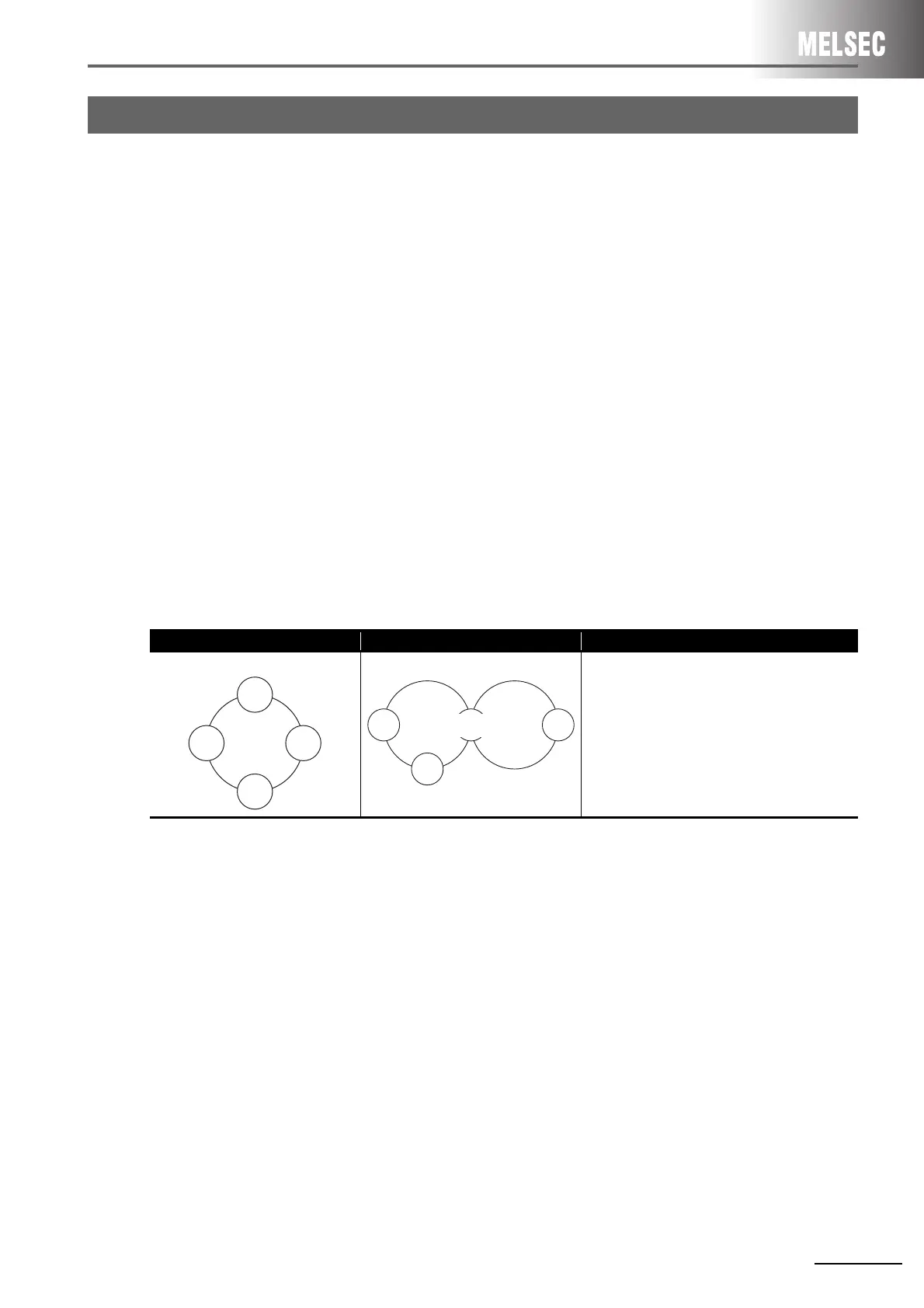
(2) System configuration
(a) System configuration using local stations and remote I/O stations in MELSECNET mode
and MELSECNET II mode
MELSECNET/H system, which is a composite system comprising local stations and remote stations,
provides high-performance functions by making a separation between local stations and remote
stations. It therefore cannot be configured by a mixture of local stations and remote stations. For this
reason, in a MELSECNET (II) system, when replacing a system, which comprises a mixture of local
stations and remote I/O stations connected to a single master station, with a MELSEC/H system, the
following system configuration is necessary. Normal stations are connected to a single control
station, and remote I/O stations are controlled by an additional remote master station (the control
station in a remote I/O system is defined as the "remote master station"). The following shows a
system configuration example.
For a parameter change example, refer to Section 3.5.2.
System configuration using local and remote stations (optical)
(b) MELSECNET (II) system comprising 65 connected modules
The maximum number of stations on the MELSECNET/H system is 64 (one control station, 63
normal stations).
The maximum number of stations on the MELSECNET (II) system is 65 (one master station, 64 local
stations + remote I/O stations). For this reason, when the maximum number of 65 MELSECNET/H
modules are connected, measures (e.g. division into two networks of 64 modules or less having a
different network No.) are required.
2.7 Replacement Precautions
MELSECNET ( II ) (optical) MELSECNET/H (optical) Remarks (proposed measure)
Optical loop
Optical loop
• The control station of network No.1
configures a PLC to PLC network that
controls normal station 1 and normal
station 2.
• The other network module becomes the
remote master station, and the remote I/O
network system of No.2 is configured.
Network
1
1N
S
1
1N
S
2
Network
2
2R3
1M
P
4/
2M
R

 Loading...


