11 DATA COMMUNICATIONS USING DC CODE TRANSMISSION CONTROL
11.1 Control Contents of DTR/DSR (ER/DR) Signal Control
237
11
11.1 Control Contents of DTR/DSR (ER/DR) Signal
Control
This control uses the RS-232 interface DTR/DSR signals to inform the target device whether or not the host station is ready to
receive data.
C24 uses the ER (DTR) signal to inform the target device whether or not the host station is ready to receive data, and uses
the DR (DSR) signal to check if the target device is ready to receive data.
C24 DTR control contents and free OS area specification
C24 DTR control contents
C24 uses the ER (DTR) signal to inform the target device whether or not it is ready to receive data.
The data transmitted from the target device using the nonprocedural protocol is stored in the receive data storage area in the
buffer memory through the OS area. (Page 53 Receiving Data from Target Device)
Under the following conditions, the received data is temporarily stored to the OS area and is transferred to the receive data
storage area when the current received data read processing is completed.
• Received data exceeding the size of the receive data storage area on the buffer memory when data, which is "receive data
storage area < receive data length", was received.
• Data received before the program reads the previously received data.
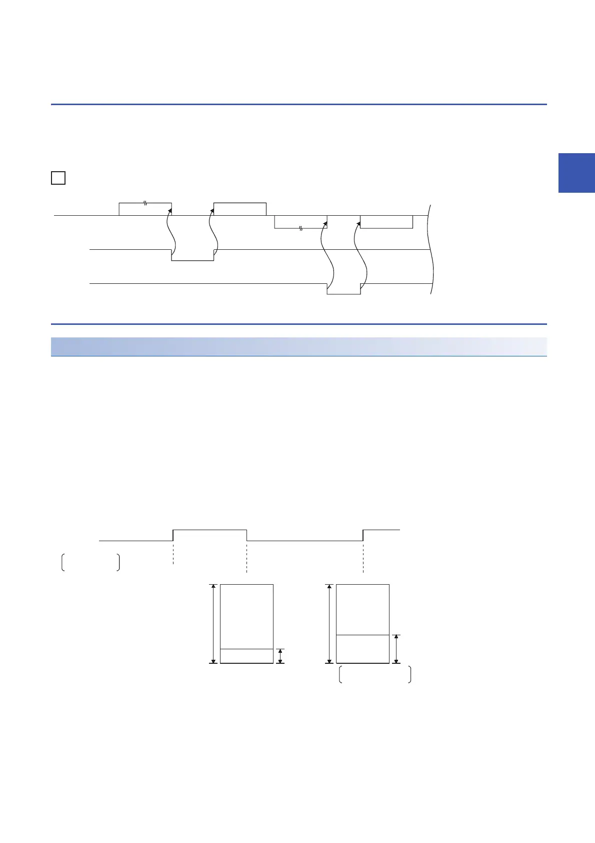
C24 turns the ER (DTR) signal ON/OFF as listed below, depending on the size of the free OS area.
• Free area is 64 bytes (default) or less: OFF
• Free area is 263 bytes (default) or more: ON
(Terminate)
(Restart)...Continue
Target device Data 1-2
Data 1-1
CPU module
Data 2-1 Data 2-2
(Restart)...Continue
(Terminate)
ER(DTR) signal
DR(DSR) signal
ON
OFF
ON
OFF
ER(DTR) signal
ON: Ready to receive
OFF: Not ready to receive
Preparation for reception
is completed
C24(OS area) C24(OS area)
(Data storage)
(Data storage)
8448
bytes
8448
bytes
263 bytes
or more
(default)
Free area
64 bytes
or less
Free area
After completion of
reading from program
(Default)
 Loading...


