EasyManuals Logo

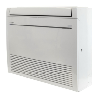
Mitsubishi Electric MFZ-KA35VA User Manual

Mitsubishi Electric MFZ-KA35VA
586 pages
To Next Page IconTo Next Page
To Previous Page IconTo Previous Page
Page #28 background imageLoading...
Page #28 background image
WALL-MOUNTED Indoor unit M series
C-26
WIRING DIAGRAM
WALL-
MOUNTED
MS-GA60VB
12V
BLK
GRY
YLW
BRN
WHT
RED
3
SR141
4
3
1
CN
121
C11
HIC1
MV1
2
1
CN112
151
CN
MV2
15
RT12
RT11
111
CN
CN211
NR11
ELECTRONIC CONTROL
P. C. BOARD
F11
L
BRN
1
2
3
CN201
MV2
CN
101
CN
102
DISPLAY
P. C. BOARD
RECEIVER
P. C. BOARD
REMOTE
CONTROLLER
33
TAB12
GRN/YLW
N
TB
2
1
2
1
CN202
TO OUTDOOR UNIT
CONNECTING
BLK
WHT
BLU
BRN
BLU
1.About the outdoor side electric wiring refer to the outdoor unit electric wiring diagram for servicing.
2.Use copper conductors only. (For field wiring)
3.Symbols below indicate.
: Connector
: Terminal block
NOTES:
SYMBOL
C11
F11
HIC1
MF
NAME
INDOOR FAN CAPACITOR
FUSE (3.15A)
DC/DC CONVERTER
INDOOR FAN MOTOR (INNER FUSE)
SYMBOL
MV1
MV2
NR11
RT11
NAME
VANE MOTOR (HORIZONTAL)
VANE MOTOR (VERTICAL)
VARISTOR
ROOM TEMPERATURE THERMISTOR
SYMBOL
RT12
SR141
TB
NAME
INDOOR COIL THERMISTOR
SOLID STATE RELAY
TERMINAL BLOCK
MF
1
2
3
4
5
6
PE
CIRCUIT
BREAKER
POWER
SUPPLY
CORD
~/N 230V
50Hz
INDOOR UNIT
MS-GD80VB MSH-GD80VB
INDOOR UNIT

Table of Contents

Other manuals for Mitsubishi Electric MFZ-KA35VA

Questions and Answers:

Question and Answer IconNeed help?

Do you have a question about the Mitsubishi Electric MFZ-KA35VA and is the answer not in the manual?

Mitsubishi Electric MFZ-KA35VA Specifications

General IconGeneral
Cooling Capacity3.5 kW
Heating Capacity4.0 kW
Power Supply220-240 V, 50 Hz
Energy Efficiency Class (Cooling)A++
Energy Efficiency Class (Heating)A+
Seasonal Energy Efficiency Ratio (SEER)6.10
Outdoor Unit Noise Level49 dB
Operating Temperature (Cooling)-10 to +46 °C
Operating Temperature (Heating)-15 to +24 °C

Related product manuals