Do you have a question about the Mitsubishi Electric MR-G50J-SS-NZ and is the answer not in the manual?
| Brand | Mitsubishi Electric |
|---|---|
| Model | MR-G50J-SS-NZ |
| Category | Refrigerator |
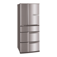
| Color | Silver |
| Finish | Stainless Steel |
| Cooling System | Multi Airflow |
| Depth | 735 mm |
| Voltage | 220-240 V |
| Frequency | 50 Hz |
| Capacity | 494L |
| Height | 1820 mm |
Details on compressor, motors, heaters, and control components.
Illustrates the overall wiring layout of refrigerator components.
Shows specific wiring connections for compartments and boards.
External dimensions, internal layout, and required installation space.
Illustrates the refrigerant flow through the system.
Explains panel operations, modes, and convenient functions.
Guides on performing self-checks and interpreting results for troubleshooting.
Details on error code display format, check points, and treatments.
Troubleshooting specific inverter-related compressor faults.
Shows functional blocks and connections on the PCB.
Flowcharts for diagnosing cooling issues in refrigerator, slide chilled, and freezer compartments.
Flowcharts for freezer cooling and compressor operation issues.
Detailed diagnosis for inverter-related compressor faults.
Continued diagnosis for inverter compressor faults.