EasyManua.ls Logo

Mitsubishi Electric Mr.Slim PEAD-RP35JALQ User Manual

Mitsubishi Electric Mr.Slim PEAD-RP35JALQ
48 pages
To Next Page IconTo Next Page
Page #1 background imageLoading...
Page #1 background image
SERVICE MANUAL
<indoor unit>
Models
PEAD-RP35JA(L)Q
PEAD-RP50JA(L)Q
PEAD-RP60JA(L)Q
PEAD-RP71JA(L)Q
PEAD-RP100JA(L)Q
PEAD-RP125JA(L)Q
PEAD-RP140JA(L)Q
TM
1. SAFETY PRECAUTION ····························· 2
2. PART NAMES AND FUNCTIONS ·············· 3
3. SPECIFICATION ········································ 5
4. FAN PERFORMANCE AND
CORRECTED AIR FLOW ·························· 8
5. SOUND PRESSURE LEVELS ···················15
6. OUTLINES & DIMENSIONS ······················22
7. WIRING DIAGRAM ····································24
8. REFRIGERANT SYSTEM DIAGRAM ········25
9. TROUBLESHOOTING ·······························26
10
. DISASSEMBLY PROCEDURE ··················40
CONTENTS
INDOOR UNIT
REMOTE CONTROLLER (option)
ON/OFF
TEMP.
Series PEAD
R410A
2010
SPLIT-TYPE, HEAT PUMP
AIR CONDITIONERS
NOTE:
This manual describes only
service data of the indoor
units.
Question and Answer IconNeed help?

Do you have a question about the Mitsubishi Electric Mr.Slim PEAD-RP35JALQ and is the answer not in the manual?

Mitsubishi Electric Mr.Slim PEAD-RP35JALQ Specifications

General IconGeneral
BrandMitsubishi Electric
ModelMr.Slim PEAD-RP35JALQ
CategoryAir Conditioner
LanguageEnglish

Summary

SAFETY PRECAUTION

General Safety Guidelines

Essential safety rules for handling the unit and its components.

R410A Refrigerant Handling Precautions

Specific safety measures for working with R410A refrigerant, including tools and procedures.

PART NAMES AND FUNCTIONS

Indoor Unit Component Identification

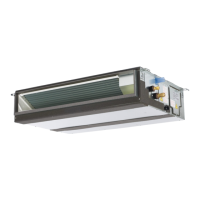
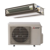
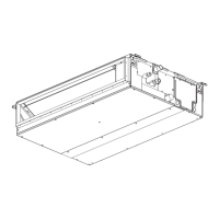
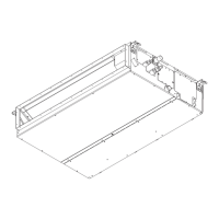
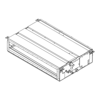
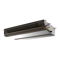
Identifies and illustrates key parts of the indoor unit for functional understanding.

SPECIFICATION

FAN PERFORMANCE AND CORRECTED AIR FLOW

SOUND PRESSURE LEVELS

OUTLINES & DIMENSIONS

Indoor Unit Physical Specifications

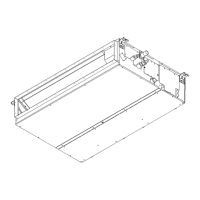
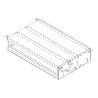
Detailed dimensions, weight, and required service space for indoor units.

WIRING DIAGRAM

REFRIGERANT SYSTEM DIAGRAM

TROUBLESHOOTING

Troubleshooting Safety Precautions

Important warnings and precautions before starting troubleshooting procedures.

Wired Remote Controller Self-Check

Guide to using the wired remote controller's self-check function for error diagnosis.

Self-Diagnosis Action Table

Comprehensive table detailing error codes, symptoms, causes, and countermeasures.

Troubleshooting Common Operational Issues

Addresses and provides solutions for various operational problems and error codes.

Electrical Test Point Locations

Identifies critical test points on circuit boards for electrical troubleshooting.

Main Component Resistance Checks

Procedures for checking the resistance of key components like thermistors.

Thermistor Characteristic Data

Provides resistance-temperature data for critical thermistors used in the unit.

DC Fan Motor Troubleshooting Guide

Step-by-step guide for diagnosing and resolving issues with the DC fan motor.

DIP Switch and Jumper Wire Settings

Explains the function of DIP switches and jumper wires for unit configuration.

DISASSEMBLY PROCEDURE

Control Box Access and Removal

Instructions for safely removing the control box cover and accessing electronics.

Intake Air Thermistor Replacement

Procedure for removing and replacing the intake air thermistor.

Drainpan and Filter Removal Procedure

Steps to remove the air filter and the drainpan for maintenance or replacement.

Condenser/Evaporator Thermistor Replacement

Steps for removing and replacing the condenser/evaporator thermistor.

Fan Motor and Fan Casing Removal

Guide for disassembling the fan motor and fan casing components.

Heat Exchanger Cover and Removal

Instructions for accessing and removing the heat exchanger assembly.

Related product manuals