Do you have a question about the Mitsubishi Electric MSH-GE50VB-E1 and is the answer not in the manual?
Details modifications made to the indoor unit models, including P.C. board and fan motor updates.
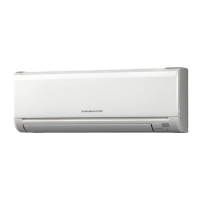
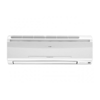
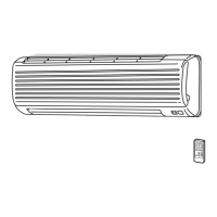
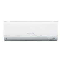
Identifies and explains components of MSC-GE20VB, MSC-GE25VB, MSC-GE35VB indoor units.
Lists and quantifies included accessories for different model series.
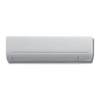
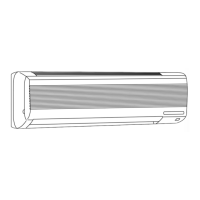
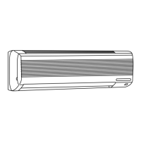
Identifies and explains components of MS-GE50VB and MSH-GE50VB indoor units.
Provides detailed technical specifications for various indoor unit models including electrical data and performance.
Displays octave band sound pressure levels for MSC-GE20VB, MSC-GE25VB, MSC-GE35VB at different fan speeds.
Displays octave band sound pressure levels for MS-GE50VB and MSH-GE50VB at different fan speeds.
Shows physical dimensions and installation details for MSC-GE20VB/25VB/35VB indoor units.
Shows physical dimensions and installation details for MS-GE50VB and MSH-GE50VB indoor units.
Illustrates electrical connections for MSC-GE series and MS/MSH-GE50VB indoor unit models.
Depicts the refrigerant flow and key components for MSC-GE series and MS/MSH-GE50VB models.
Describes how to shorten timer settings for service purposes by shorting specific pins.
Explains modifying the remote controller PC board for multi-unit operation by soldering jumper wires.
Details setting the remote controller for specific unit types (COOL & HEAT vs. COOL ONLY).
Guides on switching between MU/MUX and MUH/MXZ outdoor unit types via internal switch.
Explains the auto restart feature and how to disable it by changing switch settings.
Details disabling the auto restart function for MS/MSH-GE50VB models by soldering a jumper wire.
Illustrates buttons and functions of wireless remote controllers for different indoor unit models.
Explains the operation indicator lamp on the indoor unit and its states.
Describes the cool operation mode, including fan speed and coil frost prevention.
Details the dry operation mode, set temperature determination, and fan speed control.
Explains fan-only operation for MU/MUX models, with no outdoor unit activity.
Describes heat operation, cold air prevention, and defrosting procedures for MUH models.
Explains the 'I Feel Control' mode and its temperature determination based on room conditions.
Details initial set temperature determination based on initial room temperature for I Feel Control.
Describes temperature adjustment buttons and fuzzy control logic in 'I Feel Control' mode.
Explains horizontal vane control, positioning, auto mode, and swing modes.
Describes the energy-saving Econo Cool operation, including set temperature adjustment and vane swing.
Explains the Long mode for indoor fan speed and horizontal vane position.
Explains vertical vane control, positioning, swing, and wide modes.
Details how to set, cancel, and combine timer operations for the air conditioner.
Explains how to use the emergency operation switch for testing, servicing, and missing remote controls.
Describes the compressor protection time delay function that prevents rapid restarts.
Provides essential safety precautions and checks before starting troubleshooting procedures.
Outlines the general steps for diagnosing unit abnormalities by checking indicator lamps and connections.
Guides on how to properly replace batteries in the remote controller to ensure normal operation.
Notes on multi-system operation modes and indicator behavior when units operate simultaneously.
A decision tree for diagnosing unit malfunctions based on symptoms and error codes.
A table listing abnormalities, conditions, and remedies for specific error codes indicated by lamp flashes.
Criteria for checking resistance and voltage of key components like thermistors, motors, and fuses.
Guides for diagnosing indoor fan motor failures, including resistance and voltage checks.
Guides for diagnosing remote controller and receiver PC board issues.
Guides for checking the indoor electronic control PC board for faults and component failures.
Guides for diagnosing serial signal errors and mis-wiring between indoor and outdoor units.
Specific mis-wiring checks and procedures for MUH-GE50VB models.
Provides diagrams and voltage checks for the indoor control PC board and its components.
Explains how to detach terminals with and without locking mechanisms before disassembly.
Steps for removing the front panel and electronic control boards for MSC-GE series units.
Steps for removing the electrical box, vane motor, and fan motor for MSC-GE series units.
Steps for removing the panel and electronic control boards for MS/MSH-GE50VB units.
Steps for removing the electrical box, vane motor, and fan motor for MS/MSH-GE50VB units.
| Cooling Capacity | 5.0 kW |
|---|---|
| Heating Capacity | 5.8 kW |
| Power Supply | 220-240V, 50Hz |
| Refrigerant | R410A |
| Outdoor Unit Dimensions (W x H x D) | 800 x 550 x 285 mm |
| Weight (Indoor Unit) | 10 kg |
| COP | 3.60 |
| Operating Temperature (Heating) | -15 to 24 °C |