EasyManua.ls Logo

Mitsubishi Electric MSH15TN User Manual

Mitsubishi Electric MSH15TN
129 pages
To Next Page IconTo Next Page
Page #1 background imageLoading...
Page #1 background image
SERVICE MANUAL
SPLIT-TYPE, HEAT PUMP AIR CONDITIONERS
CONTENTS
1. FEATURES·························································2
2. TECHNICAL CHANGES ····································5
3. PART NAMES AND FUNCTIONS······················7
4. INDOOR UNIT COMBINATION························10
5. SPECIFICATION···············································11
6. DATA·································································17
7. OUTLINES AND DIMENSIONS ·······················39
8. WIRING DIAGRAM ··········································43
9. REFRIGERANT SYSTEM DIAGRAM··············51
10. MICROPROCESSOR CONTROL ····················54
11. SERVICE FUNCTIONS·····································72
12. TROUBLESHOOTING······································75
13. DISASSEMBLY INSTRUCTIONS···················101
14. PARTS LIST····················································114
15. OPTIONAL PARTS·········································126
Wireless type
Models
MSH09TW · MUH09TW
MSH12TN · MUH12TN
MSH15TN · MUH15TN
MSH17TN · MUH17TN
MSH09TW
-
· MUH09TW
-
MSH12TN
-
· MUH12TN
-
· MUH12TN
-
MSH15TN
-
· MUH15TN
-
· MUH15TN
-
MSH17TN
-
· MUH17TN
-
U1U1
U2
U1U1
U2
U1U1
U1U1
No. OB275
REVISED EDITION-D
The Slim Line.
From Mitsubishi Electric.
L
I
S
T
E
D
CUS
MSH12TN
MSH15TN
MSH17TN
INDOOR UNIT
MUH15TN
OUTDOOR UNIT
Remote
controller
MSH12TN -
MSH15TN -
MSH17TN -
U1
U1
U1
MUH15TN - MUH15TN -
U2U1
TM
Inverter-controlled multi system Model
· MXZ30TN
· MXZ30TN2
Revision:
MUH12TN- has been added.
MUH15TN- has been added.
REFRIGERANT SYSTEM DIAGRAM of
MXZ30TN and MXZ30TN2 has partly been
changed.
PARTS LIST of MXZ30TN and MXZ30TN2
has partly been changed
Please void OB275 Revised edition-C.
U2
U2
Indication of
model name
Indication of
model name
OB275--1.qxp 03.12.2 16:49 Page 1

Table of Contents

Other manuals for Mitsubishi Electric MSH15TN

Question and Answer IconNeed help?

Do you have a question about the Mitsubishi Electric MSH15TN and is the answer not in the manual?

Mitsubishi Electric MSH15TN Specifications

General IconGeneral
BrandMitsubishi Electric
ModelMSH15TN
CategoryAir Conditioner
LanguageEnglish

Summary

1 FEATURES

USA and CANADA Model Differences

Details differences between USA and CANADA models for features.

2 TECHNICAL CHANGES

Model Revision Details

Details changes made to various models including indoor and outdoor units.

3 PART NAMES AND FUNCTIONS

Indoor Unit Components

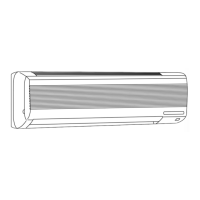
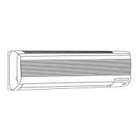
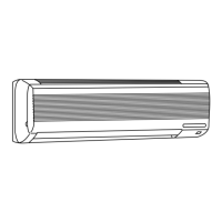
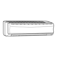
Identifies and describes parts of the indoor unit.

Unit Accessories

Lists and describes accessories provided with the units.

4 INDOOR UNITS COMBINATION

Multi-System Combinations (MXZ30TN/MXZ30TN2)

Outlines possible combinations of indoor and outdoor units for multi-system models.

5 SPECIFICATIONS

MSH09TW Specifications

Detailed specifications for the MSH09TW indoor and MUH09TW outdoor units.

Operating Range

Specifies the operating ranges for cooling and heating.

MSH12TN and MSH15TN Specifications

MSH12TN and MSH15TN Operating Range

Specifies operating ranges for MSH12TN and MSH15TN units.

MSH17TN Specifications

MSH17TN Operating Range

Specifies the operating range for MSH17TN units.

Refrigerant Piping and Height Specifications

Max. Refrigerant Piping Length

Details maximum allowed lengths for refrigerant piping.

Max. Height Difference

Specifies the maximum allowable height difference between units.

Performance Data (MXZ30TN/MXZ30TN2)

Cooling Performance Data

Presents cooling performance data for multi-system models.

Heating Performance Data

Presents heating performance data for multi-system models.

6 DATA

Performance Data (Cooling Capacity)

Detailed cooling capacity data based on various indoor/outdoor conditions.

Cooling Capacity Corrections & Heating Capacity

Provides data for cooling capacity corrections and heating capacity.

6-2. PERFORMANCE CURVE

MSH09TW/MUH09TW Performance Curves

Illustrates cooling and heating performance curves for MSH09TW/MUH09TW.

MSH12TN/MUH12TN Performance Curves

Illustrates cooling and heating performance curves for MSH12TN/MUH12TN.

MSH15TN/MUH15TN Performance Curves

Illustrates cooling and heating performance curves for MSH15TN/MUH15TN.

MSH17TN/MUH17TN Performance Curves

Illustrates cooling and heating performance curves for MSH17TN/MUH17TN.

6-3. Condensing Pressure

MSH09TW Condensing Pressure (Cooling)

Shows condensing pressure for MSH09TW in cooling mode.

MSH09TW Condensing Pressure (Heating)

Shows condensing pressure for MSH09TW in heating mode.

MSH12TN Condensing Pressure (Cooling)

Shows condensing pressure for MSH12TN in cooling mode.

MSH12TN Condensing Pressure (Heating)

Shows condensing pressure for MSH12TN in heating mode.

MSH15TN Condensing Pressure (Cooling)

Shows condensing pressure for MSH15TN in cooling mode.

MSH15TN Condensing Pressure (Heating)

Shows condensing pressure for MSH15TN in heating mode.

MSH17TN Condensing Pressure (Cooling)

Shows condensing pressure for MSH17TN in cooling mode.

MSH17TN Condensing Pressure (Heating)

Shows condensing pressure for MSH17TN in heating mode.

6-4. STANDARD OPERATION DATA

MSH09TW Standard Operation Data

Standard operational data for MSH09TW units.

MSH12TN/MSH15TN Standard Operation Data

Standard operational data for MSH12TN/MSH15TN units.

MSH17TN Standard Operation Data

Standard operational data for MSH17TN units.

Standard Operation Data (MXZ30TN/MXZ30TN2)

Standard operational data for MXZ30TN/MXZ30TN2 units.

6-5. OPERATING RANGE

Power Supply Operating Range

Details guaranteed voltage ranges for power supply.

Operational Conditions and Modes

Outlines conditions for cooling, heating, and dry modes.

Outlet Air Speed and Coverage Range

Additional Refrigerant Charge (R22)

MXZ30TN MXZ30TN2 Specifics

Guaranteed Voltage and Air Flow

Specifies guaranteed voltage and air flow settings.

Main Readings and Temperature Measurement

Defines main readings and how to measure temperature differences.

CAPACITY AND THE INPUT CURVES

Inverter Output Frequency Corrections

09-class Unit Capacity/Input Curves

Shows capacity and input corrections based on inverter frequency for 09-class units.

12-class Unit Capacity/Input Curves

Shows capacity and input corrections based on inverter frequency for 12-class units.

15-class Unit Capacity/Input Curves

Shows capacity and input corrections based on inverter frequency for 15-class units.

17-class Unit Capacity/Input Curves

Shows capacity and input corrections based on inverter frequency for 17-class units.

Outdoor Low Pressure and Unit Current

09-class Unit Cool Operation

Displays low pressure and current for 09-class unit in cool operation.

09-class Unit Heat Operation

Displays low pressure and current for 09-class unit in heat operation.

12-class Unit Cool Operation

Displays low pressure and current for 12-class unit in cool operation.

12-class Unit Heat Operation

Displays low pressure and current for 12-class unit in heat operation.

15-class Unit Cool Operation

Displays low pressure and current for 15-class unit in cool operation.

15-class Unit Heat Operation

Displays low pressure and current for 15-class unit in heat operation.

17-class Unit Cool Operation

Displays low pressure and current for 17-class unit in cool operation.

17-class Unit Heat Operation

Displays low pressure and current for 17-class unit in heat operation.

7 OUTLINES AND DIMENSIONS

Indoor Unit Dimensions

Provides dimensional drawings and measurements for the indoor unit.

Outdoor Unit Dimensions

Provides dimensional drawings and measurements for the outdoor unit.

Required Installation Space

Illustrates the necessary clearance space for installation.

8 WIRING DIAGRAM

MSH09TW/MUH09TW Wiring

Electrical wiring diagram for MSH09TW/MUH09TW models.

MSH12TN/MUH12TN Wiring

Electrical wiring diagram for MSH12TN/MUH12TN models.

MUH15TN/MUH17TN Wiring

Electrical wiring diagram for MUH15TN/MUH17TN models.

MXZ30TN/MXZ30TN2 Wiring

Electrical wiring diagram for MXZ30TN/MXZ30TN2 outdoor units.

9 REFRIGERANT SYSTEM DIAGRAM

MSH09TW/MUH09TW Refrigerant Diagram

Illustrates the refrigerant system for MSH09TW/MUH09TW units.

MSH12TN/MUH12TN Refrigerant Diagram

Illustrates the refrigerant system for MSH12TN/MUH12TN units.

MSH15TN/MUH15TN Refrigerant Diagram

Illustrates the refrigerant system for MSH15TN/MUH15TN units.

MSH17TN/MUH17TN Refrigerant Diagram

Illustrates the refrigerant system for MSH17TN/MUH17TN units.

10 MICROPROCESSOR CONTROL

Wireless Remote Controller Overview

Describes the functions and buttons of the wireless remote controller.

Indoor Unit Display Section

Explains the indicators and displays on the indoor unit.

10-1. I FEEL CONTROL OPERATION

Cool Mode I FEEL CONTROL Fan Speed

Coil Frost Prevention (Cool Mode)

Heat Mode I FEEL CONTROL Fan Speed

Dry Mode I FEEL CONTROL Fan Speed

Warm Air Control & Flow Soft Control

2. High Pressure Protection

3. Defrosting

Defrosting Entry Conditions

Lists conditions required to initiate defrosting.

Defrosting Operation Details

Describes the defrosting process and related operations.

Defrosting Finish Conditions

Lists conditions that terminate the defrosting cycle.

10-2. COOL OPERATION

10-3. DRY OPERATION

10-4. HEAT OPERATION

5. Outdoor Temperature Control

10-5. FAN MOTOR CONTROL

Rotational Frequency Feedback Control

Explains the fan motor control mechanism.

Fan Motor Lock-up Protection

Describes the protection mechanism for fan motor lock-up.

10-6. AUTO VANE OPERATION

Vane Motor Drive and Angle Control

Details vane motor drive and angle changes based on button presses.

Vane Positioning and Auto Mode

Explains vane positioning and the auto mode operation.

Vane Operation on Stop/Standby

Describes vane behavior during stop and timer standby.

Dew Prevention Function

Explains the dew prevention feature for vane angle adjustment.

SWING MODE & Cold Air Prevention (Heat)

10-7. TIMER OPERATION

Timer Setting Procedures

Details how to set ON/OFF timers.

Program Timer

Explains the program timer functionality.

10-8. EMERGENCY-TEST OPERATION

10-9. INVERTER MULTI SYSTEM CONTROL

MXZ30TN MXZ30TN2 Control Logic

Explains the control logic for multi-system inverter operation.

10-10. INVERTER MAIN POWER SUPPLY CIRCUIT

Main Power Supply Circuit Diagram

Illustrates the main power supply circuit for the inverter system.

Power Supply Circuit Operation

Explains the operation of the power supply circuit.

Power Factor Improvement

Details methods for improving power factor in the circuit.

Electrical Noise Elimination & IPM Function

10-11. Optimal Voltage Control

Purpose of Optimal Voltage Control

Explains the goal of optimal voltage control for compressor efficiency.

Determining Optimal Voltage

Describes how to determine optimal voltage based on power factor.

10-12. LEV Control

LEV Standard Opening Determination

Explains how to determine standard LEV opening.

LEV Opening Calculation Example

Provides an example calculation for LEV opening.

LEV Correction by Suction Superheat

LEV Correction by Discharge Temperature

Separate LEV Correction (Cool/Dry)

LEV Opening Correction by Discharge Temperature

10-13. Operational Frequency Range

10-14. Heat Defrosting Control

Defrosting Entry Conditions

Lists conditions required to initiate defrosting.

Defrosting Operation Details

Describes the defrosting process and related operations.

Defrosting Finish Conditions

Lists conditions that terminate the defrosting cycle.

10-15. High Pressure Protection

High Pressure Protection (Heat Mode)

Explains high pressure protection during heating operation.

High Pressure Protection (H.P.S. 63H1)

Describes high pressure protection via the HPS switch.

10-16. Discharge Temperature Protection Control

Compressor ON/OFF Control

Details compressor ON/OFF control based on discharge temperature.

Compressor Operation Frequency Control

Explains frequency control based on discharge temperature.

10-17. Refrigerant Recovery Control on Heating

10-18. Outdoor Fan Control

10-19. Relation between main sensor and actuator.

11 SERVICE FUNCTIONS

11-1. Compulsory Defrosting Mode for Service

How to activate compulsory defrosting for service.

11-2. Change in Defrost Setting

How to change defrost interval and temperature settings.

11-3. Timer Short Mode

11-4. P.C. BOARD MODIFICATION FOR INDIVIDUAL OPERATION

Modifying Remote Controller P.C. Board

Instructions for modifying remote controller P.C. boards for individual unit operation.

11-5. AUTO RESTART FUNCTION

Setting Remote Controller Exclusively

How to assign a remote controller to a specific indoor unit.

Releasing Auto Restart Function

Instructions on how to release the auto restart function.

12 TROUBLESHOOTING

Troubleshooting Procedure Overview

General steps for troubleshooting the unit.

How to Replace Batteries

Instructions for replacing remote controller batteries.

Troubleshooting Cautions

Important precautions to take before and during troubleshooting.

12-2. Instruction of Troubleshooting

Troubleshooting Flowchart (MXZ Models)

Troubleshooting Check Table

Trouble Criterion of Main Parts

Indoor Fan Motor Checks

Outdoor Fan Motor Checks

Vane Motor Checks

Check of Indoor Fan Motor

Check of Remote Controller and Receiver P.C. Board

Check of Indoor Electronic Control P.C. Board

Check of Outdoor Unit (Compressor/Fan Motor Operation)

Check Mis-wiring and Serial Signal Error

Check of Outdoor Thermistor

Check of R.V. Coil

Check of Power Supply

Check of Serial Signal

Check of R. V. Coil (Cooling/Heating Operation)

Check of LEV

Check of Inverter/Compressor

Check of Thermistor (MXZ Models)

Check of Fan Motor (MXZ Models)

Check of HPS (MXZ Models)

Other Cases (MXZ Models)

TEST POINT DIAGRAM AND VOLTAGE (MSH09TW)

Indoor Electronic Control P.C. Board (MSH09TW)

Diagram of the MSH09TW indoor control board with test points.

TEST POINT DIAGRAM AND VOLTAGE (MSH12/15/17TN)

Indoor Electronic Control P.C. Board (MSH12/15/17TN)

Diagram of MSH12/15/17TN indoor control board with test points.

Outdoor Deicer P.C. Board Diagrams

MXZ30TN Noise Filter P.C. Board

Diagram of the noise filter P.C. board for MXZ30TN.

MXZ30TN2 Noise Filter P.C. Board

Diagram of the noise filter P.C. board for MXZ30TN2.

I.P.M P.C. Board and Relay P.C. Board Diagrams

Relay Operation

Compressor Contactor Relay Operations

Details relay operations for compressor contactor by mode.

Coil Frost Prevention Relay Operations

Details relay operations during coil frost prevention.

Solid State Relay (Indoor Fan Motor Relay)

13 DISASSEMBLY INSTRUCTIONS

MSH09TW/MUH09TW Indoor Unit Disassembly

Step-by-step instructions for disassembling the MSH09TW/MUH09TW indoor unit.

Removing Electrical Box and Vane Motor

Instructions for removing the electrical box and vane motor.

Removing Fan Motor and Heat Exchanger

Instructions for removing the fan motor and heat exchanger.

MSH12/15/17TN Indoor Unit Disassembly

MUH09/12TN Outdoor Unit Cabinet and Deicer Board Removal

Removing Propeller Fan, Fan Motor, and Compressor

MUH15/17TN Outdoor Unit Cabinet and Deicer Board Removal

Removing Propeller Fan, Fan Motor, and Compressor (MUH15/17TN)

MUH17TN Outdoor Unit Disassembly Steps

Removing Heat Exchanger and Compressor (MUH17TN)

MXZ30TN/MXZ30TN2 Compressor and Fan Motor Removal

Removing 4-Way Valve, Linear Expansion Valve, and Reactor

14 PARTS LIST

Indoor Unit Structural Parts (MSH09TW)

Lists structural parts for MSH09TW indoor unit.

Accessories and Remote Controller (MSH09TW)

Lists accessories and remote controller parts for MSH09TW.

Indoor Unit Electrical & Functional Parts (MSH09TW)

Indoor Unit Heat Exchanger Parts (MSH09TW)

Outdoor Unit Parts (MUH09/12TN)

Indoor Unit Structural Parts (MSH12/15/17TN)

Accessories and Remote Controller (MSH12/15/17TN)

Indoor Unit Electrical & Functional Parts (MSH12/15/17TN)

Indoor Unit Heat Exchanger Parts (MSH12/15/17TN)

Outdoor Unit Parts (MUH15/17TN)

Outdoor Unit Parts (MUH17TN)

Outdoor Unit Functional Parts (MXZ30TN/MXZ30TN2)

Outdoor Unit Structural Parts (MXZ30TN/MXZ30TN2)

15 OPTIONAL PARTS

Refrigerant Pipes

Details optional refrigerant pipe kits and specifications.

Air Cleaning Filter

Information on the air cleaning filter and its maintenance.

Deodorizing Filter

Information on the deodorizing filter and its maintenance.

Different-Diameter Pipe Options

Lists optional pipes for connecting different diameter refrigerant pipes.

Related product manuals