CN105
CN104
When the refrigeration circuit has a leak, do not execute pump down with the
compressor.
When pumping down the refrigerant, stop the compressor before disconnecting
the refrigerant pipes. The compressor may burst if air etc. get into it.
WARNING
2-1. FIXING OF INSTALLATION PLATE
• Findastructuralmaterial(suchasastud)inthewallandxinstallationplate(1)horizon-
tallybytighteningthexingscrews(2)rmly.
• Topreventinstallationplate(1)fromvibrating,besuretoinstallthexingscrewsinthe
holesindicatedintheillustration.Foraddedsupport,xingscrewsmayalsobeinstalled
inotherholes.
• Whentheknockoutisremoved,applyvinyltapetotheknockoutedgestopreventdamag-
ingthewires.
• Whenboltsrecessedintheconcretewallaretobeutilized,secureinstallationplate(1)
using11×20·11×26ovalhole(450mmpitch).
• Iftherecessedboltistoolong,changeitforashorteroneavailableinthemarket.
2-2. WALL HOLE DRILLING
1)Determinethewallholeposition.
2)Drill aø65mmhole.Theoutdoor side should be5 to
7mmlowerthantheindoorside.
3)Insertwallholesleeve(C).
(G)
(E)
(C)
(4)
(D)
(F)
(2)
(1)
*4
(I)
(B)
(A)
(K)
(3)
(5)
1-4. INSTALLATION DIAGRAM
Whenthepipingistobeattachedtoawallcontainingmetals(tinplated)ormetal
netting,useachemicallytreatedwoodenpiece20mmorthickerbetweenthe
wallandthepipingorwrapofinsulationvinyltapearoundthepiping.
To use existing piping, perform COOL operation for 30 minutes and pump
downbeforeremovingtheoldairconditioner.Remakeareaccordingtothe
dimensionfornewrefrigerant.
clear*2
100mm
ormore
100mm
ormore
Note:
*1Place indoor/outdoor unit connecting wire (A) and
powersupplycord(K)atleast1mawayfromtheTV
antennawire.
Aftertheleaktest,applyinsulatingmaterialtightly
sothatthereisnogap.
WARNING
To avoid risk of re, embed or protect the refrigerant piping.
External damage on the refrigerant piping can be cause of re.
(6)
(J)
PARTS TO BE PROVIDED AT YOUR SITE
(A) Indoor/outdoorunitconnectingwire*1 1
(B) Extensionpipe 1
(C) Wallholesleeve 1
(D) Wallholecover 1
(E) Pipexingband 2to5
(F) Fixingscrewfor(E)4×20mm 2to5
(G) Pipingtape 1
(H) Putty 1
(I)
Drainhose
(orsoftPVChose,15mminner
diameterorhardPVCpipeVP30)
1
(J)
Drainhose
(orsoftPVChose,15mminner
diameterorhardPVCpipeVP16)
0or1
(K) Powersupplycord*1 1
ACCESSORIES
Checkthefollowingpartsbeforeinstallation.
<Indoorunit>
(1) Installationplate 1
(2)
Installationplatexingscrew
4×25mm
5
(3) Wirelessremotecontroller 1
(4)
Felttape
(Forleftorleft-rearpiping)
1
(5) Battery(AAA)for(3) 2
<Outdoorunit>
(6) Drainsocket 1
IMPORTANT NOTES
Checkthatcablingwillnotbesubjecttowear,corrosion,excessivepressure,
vibration,sharpedgesoranyotheradverseenvironmentaleects.Thecheck
shallalsotakeintoaccounttheeectsofagingorcontinualvibrationfrom
sourcessuchascompressorsorfans.
350mm
ormore
Note:
Installtheunithorizontally.
Donotusedrainsocket(6)incoldregions.Drainmayfreezeandmakethe
fanstop.
Theoutdoorunitproducescondensateduringtheheatingoperation.Select
theinstallationplacetoensuretopreventtheoutdoorunitand/orthegrounds
frombeingwetbydrainwaterordamagedbyfrozendrainwater.
Drain piping for outdoor unit
•Providedrainpipingbeforeindoorandoutdoorpip-
ingconnection.
•Connectdrainhose(J)I.D.15mmasshowninthe
illustration.
• Make sure to provide drain piping with a downhill
gradeforeasydrainow.
2. INDOOR UNIT INSTALLATION
Wall
Outdoor
side
ø65mm
5-7mm
Burr
Copperpipe
Sparereamer
Pipecutter
3-2. FLARING WORK
1)Cutthecopperpipecorrectlywithpipecutter.(Fig.1,2)
2)Completelyremoveallburrsfromthecutcrosssection
ofpipe.(Fig.3)
• Puttheendofthecopperpipetodownwarddirection
asyouremoveburrsinordertoavoidtoletburrsdrop
inthepiping.
3)Removearenutsattachedtoindoorandoutdoorunits,
thenputthemonpipehavingcompletedburrremoval.
(Notpossibletoputthemonafteraringwork.)
4)Flaringwork(Fig.4,5).Firmlyholdcopperpipeinthe
dimensionshowninthetable.SelectAmmfromthetable
accordingtothetoolyouuse.
5)Check
• ComparethearedworkwithFig.6.
• Ifareisnotedtobedefective,cutothearedsec-
tionanddoaringworkagain.
Pipediameter
(mm)
Nut
(mm)
A(mm) Tighteningtorque
Clutch
typetool
forR32,
R410A
Clutch
typetool
forR22
Wing nut
typetool
forR22
N•m kgf•cm
ø6.35(1/4”) 17
0to0.5 1.0to1.5
1.5to2.0
13.7to
17.7
140to
180
ø9.52(3/8”) 22
34.3to
41.2
350to
420
ø12.7(1/2”) 26
2.0to2.5
49.0to
56.4
500to
575
ø15.88(5/8”) 29
73.5to
78.4
750to
800
Copper
pipe
Good
TiltedUnevenBurred
Nogood
Fig.1
Fig.2
Clutchtype
Flaringtool
Fig.4Fig.3
Smoothall
around
Evenlength
allaround
Inside is shin-
ingwithoutany
scratches.
Flare nut
Die
Fig.5 Fig.6
3. OUTDOOR UNIT INSTALLATION
Copperpipe
Wingnuttype
3-1. CONNECTING WIRES FOR THE OUTDOOR UNIT
1)Opentheservicepanel.
2)Loosenterminalscrew, andconnectindoor/outdoor unitconnectingwire (A)fromthe
indoorunitcorrectlyontheterminalblock.Becarefulnottomakemis-wiring.Fixthewire
totheterminalblocksecurelysothatnopartofitscoreisappeared,andnoexternalforce
isconveyedtotheconnectingsectionoftheterminalblock.
3)Firmlytightentheterminalscrewstopreventthemfromloosening.Aftertightening,pull
thewireslightlytoconrmthattheydonotmove.
4)Connectpowersupplycord(K).
5)
Fixindoor/outdoorunitconnectingwire(A)andpowersupplycord(K)withthecordclamp.
6)Closetheservicepanelsecurely.
• Makeearthwirelongerthanothersaspicture.
• Forfutureservicing,giveextralengthtotheconnectingwires.
• Besuretoattacheachscrewtoitscorrespondentterminalwhensecuringthecord
and/orthewiretotheterminalblock.
3-4. INSULATION AND TAPING
1)Coverpipingjointswithpipecover.
2)Foroutdoorunitside,surelyinsulateeverypipingincludingvalves.
3)Usingpipingtape(G),applytapingstartingfromtheentryofoutdoorunit.
• Stoptheendofpipingtape(G)withtape(withadhesiveagentattached).
• Whenpipinghavetobearrangedthroughaboveceiling,closetorwherethetempera-
ture and humidity are high, wind additional commercially sold insulation to prevent
condensation.
4-1. PURGING PROCEDURES AND LEAK TEST
1)Removeserviceportcapofstopvalveonthesideoftheoutdoorunitgaspipe.(Thestop
valvesarefullyclosedandcoveredincapsininitialstate.)
2)Connectgaugemanifoldvalveandvacuumpumptoserviceportofstopvalveonthegas
pipesideoftheoutdoorunit.
4-2. TEST RUN
1)Insertpowersupplyplugintothepoweroutletand/orturnonthe
breaker.
2)PressingtheE.O.SWwillperformatestrunfor30minutes.
(ForMSZ,pressingtheswitchoncewillperformCOOLoperation
andtwicewillperformHEAToperation.)Iftheupperlampofthe
operationindicatorblinksevery0.5seconds,inspecttheindoor/
outdoorunitconnectingwire(A)formis-wiring.Afterthetestrun,
emergencymode(settemperature24ºC)willstart.
3)Tostopoperation,presstheE.O.SWseveraltimesuntilallLED
lampsturno.Refertooperatinginstructionsfordetails.
4)Checkingtheremote(infrared)signalreception
• Press the OFF/ON button on the remote controller (3) and
checkthatanelectronicsoundisheardfromtheindoorunit.
PresstheOFF/ONbuttonagaintoturntheairconditionero.
• Once the compressor stops, the restart preventive device
operatessothecompressorwillnotoperatefor3
minutesto
protecttheairconditioner.
Stopvalvefor
GAS
Stopvalvecap
(Torque19.6to
29.4N•m,200
to300kgf•cm)
Vacuumpump(orthevacuum
pumpwiththefunctionto
preventthebackow)
Gaugemanifoldvalve
(forR32,R410A)
Compoundpressuregauge
(forR32,R410A)
–0.101MPa
(
–760mmHg)
Handle
Low
Handle High
Adapterfor
preventingthe
backow
Chargehose
(forR32,R410A)
Hexagonalwrench
Precautionswhenusingthecontrolvalve
When attaching the control valve
totheserviceport, valve coremay
deformorloosenifexcesspressure
isapplied.Thismaycausegasleak.
Serviceport
Body
Close
Open
Control
valve
A
Whenattachingthecontrolvalveto
theserviceport,makesurethatthe
valvecoreisinclosedposition,and
then tighten part A. Do not tighten
partA orturnthebody whenvalve
coreisinopenposition.
Serviceportcap
(Torque13.7to
17.7N•m,140to
180kgf•cm)
3)Runthevacuumpump.(Vacuumizeuntil500micronsisachieved.)
4)Checkthevacuumwithgaugemanifoldvalve,thenclosegaugemanifoldvalve,andstop
thevacuumpump.
5)Leaveasitisforoneortwominutes.Makesurepointergaugemanifoldvalveremains
inthesameposition.Conrmthatpressure
gaugeshows–0.101MPa[Gauge](–760
mmHg).
6)Removegaugemanifoldvalvequicklyfromserviceportofstopvalve.
Stopvalve
forLIQUID
Caution:
• Aftertestrunorremotesignalreceptioncheck,turnotheunitwiththeE.O.SWor
theremotecontrollerbeforeturningothepowersupply.Notdoingsowillcausethe
unittostartoperationautomaticallywhenpowersupplyisresumed.
To the user
• Afterinstallingtheunit,makesuretoexplaintheuseraboutautorestartfunction.
• If auto restart function is unnecessary, it can be deactivated. Consult the service
representativetodeactivatethefunction.Refertotheservicemanualfordetails.
4. PURGING PROCEDURES, LEAK TEST, AND TEST RUN
Pressuregauge
(forR32,R410A)
Charge
hose
4-4. EXPLANATION TO THE USER
• UsingtheOPERATINGINSTRUCTIONS,explaintotheuserhowtousetheairconditioner
(howtousetheremotecontroller,howtoremovetheairlters,howtoclean,precautions
foroperation,etc.).
• RecommendtheusertoreadtheOPERATINGINSTRUCTIONScarefully.
WARNING
To avoid risk of re, make sure that there are no ammable hazards or ignition
risks before opening the stop valves.
7)Afterrefrigerantpipesareconnectedandevacuated,fullyopenthevalvestemofallstop
valvesonbothsidesofgaspipeandliquidpipebythehexagonalwrench.Ifthevalve
stemhitsthestopper,donotturnitanyfurther.Operatingwithoutfullyopeninglowers
theperformanceandthiscausestrouble.
8)Referto1-3.,andchargetheprescribedamountofrefrigerantifneeded.Besuretocharge
slowlywithliquidrefrigerant.Otherwise,compositionoftherefrigerantinthesystemmay
bechangedandaectperformanceoftheairconditioner.
9)Tightencapofserviceporttoobtaintheinitialstatus.
10)Leaktest
4-3. AUTO RESTART FUNCTION
Thisproductisequippedwithanautorestartfunction.Whenthepowersupplyisstopped
duringoperation,suchasduringblackouts,thefunctionautomaticallystartsoperationin
theprevioussettingoncethepowersupplyisresumed.(Refertotheoperatinginstructions
fordetails.)
Besuretousewallholesleeve(C)
topreventindoor/outdoorconnect-
ingwire(A)fromcontactingmetal
parts in the wall and to prevent
damage by rodents in case the
wallishollow.
Indoorunit
Wallhole
sleeve(C)
Cutothe
extralength.
Pipexingband(E)
Wallholecover(D)
Fixingscrew(F)
Thisproductisdesignedandintendedforuseintheresidential,commercial
andlight-industrialenvironment.
HEADOFFICE:TOKYOBUILDING,2-7-3,MARUNOUCHI,CHIYODA-KU,
TOKYO100-8310,JAPAN
7. CONNECTING THE INTERFACE/CONNECTOR CABLE TO THE AIR CONDITIONER
Fix the connecting cable at the prescribed position securely. Incorrect installation
may cause electric shock, re, and/or malfunction.
WARNING
Sealthewallhole
gapwithputty(H).
Fixthepipetowall
withpipexingband
(E).
153mm
ormore
59
mmormore/
145
mmormore
forleft/leftrearpiping
(usingspacer)
163
mm
ormore
11mm
ormore
1.8mormorefromtheoor.
Upto2.3misrecommended.
Installationplate(1)
Centerof
ø65mmhole
163 mm
ormore
153 mm
ormore
Ceiling
Wall
Wall
Fixing
screw(2)
Insertthescale.*
Alignthe
scale with
theline.*
100mm
Level
*Sameforlefthole.
Emergencyoperation
switch(E.O.SW)
59mmormore
145mmormoreforleft/leftrear
piping(usingspacer)
• ConnecttheINTERFACE/CONNECTORCABLEtotheIndoorelectroniccontrolP.C.boardoftheairconditionerwiththeconnectingcable.
• CuttingorextendingtheconnectingcableoftheINTERFACE/CONNECTORCABLEresultsindefectsinconnecting.
Donotbundletheconnectingcabletogetherwithpowersupplycord,indoor/outdoorconnectingwire,and/orearthwire.Keepasmuchdistanceaspossiblebetweenthe
connectingcableandthosewires.
• Thethinpartoftheconnectingcableshouldbestoredandplacedwherecustomerscannottouchit.
1) Removethepanelandthelowerrightcornerbox.
2)OpenthecoversoftheIndoorelectroniccontrolP.C. board.
3)ConnecttheconnectingcabletoCN105*and/orCN104ontheIndoorelectroniccontrolP.C. board.
Passthethinpartoftheconnectingcablethroughtheribasshowninthegure.
4)AttachthecableclampprovidedwithInterfacetothethickpartoftheconnectingcablewithascrew4×16asshownin
thegure.
5)Passtheconnectingcablethroughtheribasshowninthegure.
6)ClosethecoversoftheIndoorelectroniccontrolP. C.board.Becarefulnottocatchthethinpartoftheconnecting
cableinthecover.Reinstallthepanelandthelowerrightcornerbox.
Airconditioner
Thinpartoftheconnectingcable.
Placethispartwherecustomerscannottouchit.
Thickpartoftheconnectingcable
Indoorelectronic
controlP.C.board
CN105*forINTERFACE
CN104forCONNECTORCABLE
Connecting
5. CONNECTION SETUP OF THE Wi-Fi INTERFACE (VFK type only)
ThisproductisequippedwiththeWi-FiInterfaceasstandard.
RefertotheSETUPQUICKREFERENCEGUIDEandOPERATINGINSTRUCTIONSprovidedwiththeindoorunitforconnectionwiththerouter.
6-1. REMOVING AND INSTALLING THE PANEL ASSEM
BLY 6-3. PUMPING DOWN
Whenrelocatingordisposingoftheairconditioner,pumpdownthesystemfollowing
theprocedurebelowsothatnorefrigerantisreleasedintotheatmosphere.
1)Connectthegaugemanifoldvalvetotheserviceportofthestopvalveonthegas
pipesideoftheoutdoorunit.
2)Fullyclosethestopvalveontheliquidpipesideoftheoutdoorunit.
3)Closethestopvalveonthegaspipesideoftheoutdoorunitalmostcompletelyso
thatitcanbeeasilyclosedfullywhenthepressuregaugeshows0MPa[Gauge](0
kgf/cm²).
4)StarttheemergencyCOOLoperation.
TostarttheemergencyoperationinCOOLmode,disconnectthepowersupplyplug
and/orturnothebreaker.After15seconds,connectthepowersupplyplugand/
orturnonthebreaker,andthenpresstheE.O.SWonce.(TheemergencyCOOL
operationcanbeperformedcontinuouslyforupto30minutes.)
5)Fullyclosethestopvalveonthegaspipesideoftheoutdoorunitwhenthepressure
gaugeshows0.05
to0MPa[Gauge](approx.0.5to0kgf/cm²).
6)StoptheemergencyCOOLoperation.
Press the E.O. SW several times until all LED lamps turn o. Refer to operating
instructionsfordetails.
6. RELOCATION AND MAINTENANCE
Removal procedure
1)Removethe2screwswhichxthepanelassembly.
2)Removethepanelassembly.Besuretoremoveits
bottomendrst.
Installation procedure
1)Install the panel assembly following the removal
procedureinreverse.
2)Be sure to press the positions as indicated by the
arrowsinordertoattachtheassemblycompletelyto
theunit.
6-2. REMOVING THE INDOOR UNIT
Removethebottomoftheindoorunitfromtheinstal-
lationplate.
Releasebothleftandrightbottompartofindoorunit
andpullitdownwardandforwardasshowninthe
gureontheright.
Close
Open
Valvestem(inside)
Power supply cord (K)
Earth wire
15mm
35mm
100mm
ormore
Others
15mm
35mm
WARNING
When installing the unit, securely connect the refrigerant pipes before starting
the compressor.
Outdoor unit connection
Connectpipestostopvalvepipejointoftheoutdoorunitinthesamemannerappliedfor
indoorunit.
• Fortightening, use atorque wrenchor spannerand usethesame tighteningtorque
appliedforindoorunit.
3mmorless
3-3. PIPE CONNECTION
• Fastenarenutwithatorquewrenchasspeciedinthetable.
• Whenfastenedtootight,arenutmaybreakafteralongperiodandcauserefrigerant
leakage.
• Besuretowrapinsulationaroundthepiping. Directcontactwiththebarepipingmay
resultinburnsorfrostbite.
• Usearednutinstalledtothisindoorunit.
Indoor unit connection
Connectbothliquidandgaspipingstoindoorunit.
• Donotapplyrefrigerationoilonscrewthreads.Excessivetighteningtorquewillresultin
damageonthescrew.
• Forconnection,rstalignthecenter,thentightentherst3to4turnsofarenutbyhand.
• Usetighteningtorquetableaboveasaguidelineforindoorunitsideunionjointsection,
andtightenusingtwowrenches.Excessivetighteningdamagesthearesection.
Flare nut Unionjoint
ExternalthreadsideInternal thread side
Tightenthearenut
withatorquewrench.
Gripthenutonthe
unionjointwithaspanner.
5mmorless
Drain Piping
• Donotcutthedrainhoseoftheunit.(Fig.1)
• Iftheextensiondrainhosehastopassthrougharoom,besuretowrapitwithcom-
merciallysoldinsulation.
• Thedrainhoseshouldpointdownwardforeasydrainow.(Fig.2)
• Ifthedrainhoseprovidedwiththeindoorunitistooshort,connectitwithdrainhose
(I)thatshouldbeprovidedatyoursite.(Fig.3)
• Whenconnectingthedrainhosetothehardvinylchloridepipe,besuretoinsertit
securelyintothepipe.(Fig.4)
• Makesurethatnostressisappliedtotheconnectingportionofthedrainhoseafter
installingtheindoorunit.Otherwise,breakageorwaterleakagemayresult.
• Besuretousethedrainhoseattachedtotheindoorunit.Otherwise,waterleakage
orbreakageduetochemicalmayresult.
• Donotapplyanyagentonthedrainport.Doingsomaycausebreakage.
Donotmakedrainpipingasshownbelow.
Downward
slope
Drain
hose
Softhose
I.D.15mm
Drainhose
Hardvinylchloride
pipeI.D.30mm
Insert
securely
Dierent
diameterjoint
70cm
ormore
Fig.2 Fig.3 Fig.4
Fig.1
Felttape(4)
Pipingtape(G)
Cutoincaseof
leftpiping.
Draincap
Draincap
Drainhose
Draincap
Drainhose
Fig.1
Fig.2
Fig.3
Fig.4
Fig.5
1)Puttherefrigerantpipingandthedrainhosetogether,
thenrmlyapplyfelttape(4)fromtheend.
Felttape(4)overlapwidthshouldbe1/3thetapewidth.
Useabandagestopperattheendoffelttape(4).
2)Pulloutthedraincapattherearrightoftheindoor
unit.(Fig.1)
• Hold the convex section at the end and pull the
draincap.
3)Pulloutthedrain hoseattherearleft of theindoor
unit.(Fig.2)
• Holdtheclawmarkedbythearrowsandpullout
thedrainhoseforward.
4)Putthedraincapintothesectiontowhichthedrain
hoseistobeattachedattherearoftheindoorunit.
(Fig.3)
• Insertnotsharp-edgedtoolssuchasscrewdrivers
intotheholeattheendofthecapandinsertthe
capfullyintothedrainpan.
5)Insertthedrainhosefullyintothedrainpanattherear
rightoftheindoorunit.(Fig.4)
• Checkifthehoseishookedsecurelytotheprojec-
tionofitsinsertingpartatthedrainpan.
6)Insert thedrain hose into wallhole sleeve (C),
and
hooktheupperpartofindoorunitoninstallationplate
(1).Then,movetheindoorunitcompletelytotheleft
inordertomakeplacingthepipinginthebackspace
oftheuniteasier.
7)Cutoutapieceofcardboardfromtheshippingbox,roll
itup,hookitontothebackrib,anduseitasaspacer
tolifttheindoorunit.(Fig.5)
8)Connecttherefrigerantpipingwiththeextensionpipe
(B).
9)Thrustthelowerpartoftheindoorunitintotheinstal-
lationplate(1).
Left or left-rear piping
Note:
Besuretoreattachthedrainhose
andthedraincapincaseofleftor
left-rearpiping.
Otherwise, it could cause drops
of water to drip down from the
drainhose.
Donotraise
Accumulated
drain water
Air
Waving
Water
leakage
Water
leakage
Water
leakage
Tipofdrain
hosedipped
in water
Ditch
Atleast
50mm
gap
2-4. PIPE FORMING AND DRAIN PIPING
Pipe Forming
• Placethedrainhosebelowtherefrigerantpiping.
• Makesurethatthedrainhoseisnotheavedorsnaked.
• Donotpullthehosewhenapplyingthetape.
• When the drain hose passes the room, be sure to wrap
insulationmaterial(obtainableatastore)aroundit.
Rear, right, or downward piping
1)Puttherefrigerantpipingandthedrainhose
together,thenrmlyapplypipingtape(G)from
theend.
2)Insertthepipingandthedrainhoseintothe
wallholesleeve(C),andhooktheupperpart
oftheindoorunitontheinstallationplate(1).
3)Checkiftheindoorunitishookedsecurelyontheinstallationplate(1)bymoving
theunittoleftandright.
4)Thrustthelowerpartoftheindoorunitintotheinstallationplate(1).
Liquidpipe
Gaspipe
Felttape(4)
Indoor/outdoorunit
connectingwire(A)
Pipingtape(G)
Cutoincaseof
rightpiping.
Cutoincaseof
downwardpiping.
2-3. CONNECTING WIRES FOR THE INDOOR UNIT
Youcanconnectindoor/outdoorleadwirewithoutremovingthefrontpanel.
1)Openthefrontpanel.
2)RemoveVAclamp.
3)Passindoor/outdoorunitconnectingwire(A)fromthebackoftheindoorunitandprocess
theendofthewire.
4)Loosenterminalscrew,andconnectrsttheearthwire,thenindoor/outdoorunitcon-
nectingwire(A)totheterminalblock.Becarefulnottomakemis-wiring.Fixthewireto
theterminalblocksecurelysothatnopartofitscoreisappeared,andnoexternalforce
isconveyedtotheconnectingsectionoftheterminalblock.
5)Firmlytightentheterminalscrewstopreventthemfromloosening.Aftertightening,pull
thewireslightlytoconrmthattheydonotmove.
6)Secureindoor/outdoorunitconnectingwire(A)andtheearthwirewiththeVAclamp.
NeverfailtohooktheclawoftheVAclamp.AttachtheVAclampsecurely.
• Forfutureservicing,giveextralengthtotheconnectingwires.
• Makeearthwirelongerthanothersaspicture.
• Donotfoldtheexcesswire,orcramitintosmallspace.Takecautionnottodamage
thewires.
• Besuretoattacheachscrew
toitscorrespondentterminalwhensecuringthecord
and/orthewiretotheterminalblock.
Note:Donotplacethe wires betweentheindoorunit and theinstallationplate(1).
Damagedwirecouldcauseheatgenerationorre.
Earth wire
15mm
35mm
60mm
ormore
Others
15mm
35mm
Indoorterminalblock
Indoor/outdoor
unitconnecting
wire (A)
Outdoorterminalblock
Earth wire
(green/yellow)
S1 S2 S3
S1 S2 S3
Covertheconnectionpartwithtapetopreventwaterfromleaking.
Donotblocktheinletoftheoutdoorunitwiththeexcesspartofthepipes.
*DonotholdtheApartwheninstalling/remov-
ingorcarryingthepanel,orthepanelmightbe
damaged.
Apart:lowerpartofair
outletofthepanel
JG79N606H01
Required Tools for Installation
Phillipsscrewdriver
Level
Scale
Utilityknifeorscissors
65mmholesaw
Torquewrench
Wrench(orspanner)
4mmhexagonalwrench
FlaretoolforR32,R410A
GaugemanifoldforR32,R410A
VacuumpumpforR32,R410A
ChargehoseforR32,R410A
Pipecutterwithreamer
ENGLISH
REFRIGERANT
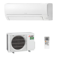
SPLIT-TYPE AIR CONDITIONERS
INSTALLATION MANUAL
Model names are indicated in 1-3.
Wheninstallingmultiunits,refertothe
installationmanualofthemultiunitfor
outdoorunitinstallation.
English is
original.
1. BEFORE INSTALLATION
MEANINGS OF SYMBOLS DISPLAYED ON INDOOR UNIT AND/OR OUTDOOR UNIT
WARNING
(Riskofre)
Thisunitusesaammablerefrigerant.
Ifrefrigerantleaksandcomesincontactwithreorheatingpart,itwillcreateharmfulgasandthereisriskofre.
ReadtheOPERATINGINSTRUCTIONScarefullybeforeoperation.
ServicepersonnelarerequiredtocarefullyreadtheOPERATINGINSTRUCTIONSandINSTALLATIONMANUALbeforeoperation.
FurtherinformationisavailableintheOPERATINGINSTRUCTIONS,INSTALLATIONMANUAL,andthelike.
1-1. THE FOLLOWING SHOULD ALWAYS BE OBSERVED FOR SAFETY
• Besuretoread“THEFOLLOWINGSHOULDALWAYSBEOBSERVEDFORSAFETY”beforeinstallingtheairconditioner.
• BeforestartingtheconnectionsetupoftheWi-Fiinterface,checkthesafetyprecautionsinOPERATINGINSTRUCTIONSoftheroomairconditioner.Wi-Fi
®
is a registered
trademarkofWi-FiAlliance
®
.
• Besuretoobservethewarningsandcautionsspeciedhereastheyincludeimportantitemsrelatedtosafety.
• Afterreadingthismanual,besuretokeepittogetherwiththeOPERATINGINSTRUCTIONSforfuturereference.
WARNING
(Couldleadtodeath,seriousinjury,etc.)
■Do not install the unit by yourself (user).
Incompleteinstallationcouldcausere,electricshock,
injuryduetotheunitfalling,orleakageofwater.Con-
sultthedealerfromwhomyoupurchasedtheunitora
qualiedinstaller.
■Perform the installation securely referring to the
installation manual.
Incompleteinstallationcouldcausere,electricshock,
injuryduetotheunitfalling,orleakageofwater.
■When installing the unit, use appropriate protective
equipment and tools for safety.
Failuretodosocouldcauseinjury.
■Install the unit securely in a place which can bear
the weight of the unit.
Iftheinstallationlocationcannotbeartheweightofthe
unit,theunitcouldfallcausinginjury.
■Do not alter the unit.
Itmaycausere,electricshock,injuryorwaterleakage.
■Electrical work should be performed by a qualied,
experienced electrician, according to the installation
manual. Be sure to use an exclusive circuit. Do not
connect other electrical appliances to the circuit.
Ifthecapacityofthepowercircuitisinsucientorthere
isincompleteelectricalwork,itcouldresultinareor
anelectricshock.
■Earth the unit correctly.
Do not connect the earth to a gas pipe, water pipe,
lightning rod, or telephone earth. Defective earthing
couldcauseelectricshock.
■Do not damage the wires by applying excessive
pressure with parts or screws.
Damagedwirescouldcausereorelectricshock.
■Be sure to cut o the main power in case of setting
up the indoor P.C. board or wiring works.
Failuretodosocouldcauseelectricshock.
■Use the specied wires to connect the indoor and
outdoor units securely and attach the wires rmly to
the terminal block connecting sections so the stress
of the wires is not applied to the sections. Do not
extend the wires, or use intermediate connection.
Incompleteconnectingandsecuringcouldcausere.
■Do not install the unit in a place where ammable
gas may leak.
Ifgas leaksand accumulatesin thearea around the
unit,itcouldcauseanexplosion.
■Do not use intermediate connection of the power
cord or the extension cord and do not connect many
devices to one AC outlet.
Itcouldcauseareoranelectricshockdueto
defective
contact,defectiveinsulation,exceedingthepermissible
current,etc.
■Be sure to use the parts provided or specied parts
for the installation work.
The use of defective parts could cause an injury or
leakageof waterdue toa re, anelectric shock,the
unitfalling,etc.
■When plugging the power supply plug into the
outlet, make sure that there is no dust, clogging,
or loose parts in both the outlet and the plug. Make
sure that the power supply plug is pushed com-
pletely into the outlet.
Ifthereisdust,clogging,orloosepartsonthepower
supplyplugortheoutlet,itcouldcauseelectricshockor
re.Ifloosepartsarefoundonthepowersupplyplug,
replaceit.
■Attach the electrical cover to the indoor unit and the
service panel to the outdoor unit securely.
Iftheelectricalcoveroftheindoorunitand/ortheservice
paneloftheoutdoorunitarenotattachedsecurely,it
couldresultinareoranelectricshockduetodust,
water,etc.
■When installing, relocating, or servicing the unit,
make sure that no substance other than the speci-
ed refrigerant (R32) enters the refrigerant circuit.
Any presence of foreign substance such as air can
causeabnormalpressureriseandmayresultinexplo-
sionorinjury.Theuseofanyrefrigerantotherthanthat
speciedforthesystemwillcausemechanicalfailure,
system malfunction, or unit breakdown. In the worst
case,thiscouldleadtoaseriousimpedimenttosecuring
productsafety.
■Do not discharge the refrigerant into the atmos-
phere. If refrigerant leaks during installation, ven-
tilate the room. Check that the refrigerant does not
leak after installation has been completed.
If refrigerant leaks and comes in contact with re or
heatingpartofsuchafanheater,keroseneheater,or
cookingstove,itwillcreateharmfulgas.Provideventila-
tion
inaccordancewithEN378-1.
■Use appropriate tools and piping materials for instal-
lation.
ThepressureofR32is1.6timesmorethanR22.Not
using appropriate tools or materials and incomplete
installationcouldcausethepipestoburstorinjury.
■When pumping down the refrigerant, stop the com-
pressor before disconnecting the refrigerant pipes.
If the refrigerant pipes are disconnected while the
compressorisrunningandthestopvalveisopen,air
couldbedrawninandthepressureintherefrigeration
cyclecouldbecomeabnormallyhigh.Thiscouldcause
thepipestoburstorinjury.
■When installing the unit, securely connect the re-
frigerant pipes before starting the compressor.
Ifthecompressorisstartedbeforetherefrigerantpipes
areconnectedandwhenthestopvalveisopen,aircould
bedrawninandthepressureintherefrigerationcycle
couldbecomeabnormallyhigh.Thiscouldcausethe
pipestoburstorinjury.
■Fasten a are nut with a torque wrench as specied
in this manual.
Iffastenedtootight,aarenutmaybreakafteralong
periodandcauserefrigerantleakage.
■The unit shall be installed in accordance with na-
tional wiring regulations.
■When using a gas burner or other ame-producing
equipment, completely remove all of the refrigerant
from the air conditioner and ensure that the area is
well-ventilated.
Iftherefrigerantleaksandcomesincontactinreor
heatingpart,itwillcreateharmfulgasandthereisrisk
ofre.
■Do not use means to accelerate the defrosting pro-
cess or to clean, other than those recommended by
the manufacturer.
■The appliance shall be stored in a room without
continuously operating ignition sources (for exam-
ple: open ames, an operating gas appliance or an
operating electric heater).
■Do not pierce or burn.
■Be aware that refrigerants may not contain an odour.
■Pipe-work shall be protected from physical damage.
■The installation of pipe-work shall be kept to a
minimum.
■Compliance with national gas regulations shall be
observed.
■Keep any required ventilation openings clear of
obstruction.
For Wi-Fi interface
■Do not install the indoor unit equipped with the Wi-Fi
interface nearby the automatic control devices such
as automatic doors or re alarms.
Itcancauseaccidentsduetomalfunctions.
■Do not use the indoor unit equipped with the Wi-Fi
interface nearby the medical electrical equipment
or people who have a medical device such as a
cardiac pacemaker or an implantable cardioverter-
debrillator.
It can cause an accident due to malfunctions of
the
medicalequipmentordevice.
■This indoor unit equipped with the Wi-Fi interface
should be installed and operated with a minimum
distance of 20 cm between the device and the user
or bystanders.
1-2. SELECTING THE INSTALLATION LOCATION
1-3. SPECIFICATIONS
Model Powersupply*1 Wirespecications
Pipesize
(thickness*3,*4)
Maximumamountof
refrigerantcharge*7
Indoorunit Outdoorunit RatedVoltage Frequency
Breaker
capacity
Powersupply*2
Indoor/outdoor
connectingwire*2
Gas/Liquid
MSZ-HR25VF(K) MUZ-HR25VF
230V 50Hz
10A
3-core
1.0mm²
4-core
1.0mm²
ø9.52/6.35mm
(0.8mm)
660g
MSZ-HR35VF(K) MUZ-HR35VF 710g
MSZ-HR42VF(K) MUZ-HR42VF 960g
MSZ-HR50VF(K) MUZ-HR50VF 12A
3-core
1.5mm²
1060g
Pipelengthandheightdierence
Max.pipelength 20m
Max.heightdierence 12m
Max.numberofbends*5,*6 10
RefrigerantadjustmentA*7 20g/m
Insulationthickness*8,*9 8mm
INDOOR UNIT
*1Connecttothepowerswitchwhichhasagapof3mmormorewhenopentointerruptthesourcepowerphase.(Whenthe
powerswitchisshuto,itmustinterruptallphases.)
*2Usewiresinconformitywithdesign60245IEC57.
*3Neverusepipeswiththicknesslessthanspecied.Thepressureresistancewillbeinsucient.
*4Useacopperpipeoracopper-alloyseamlesspipe.
*5Becarefulnottocrushorbendthepipeduringpipebending.
*6Refrigerantpipebendingradiusmustbe100mmormore.
*7Ifpipelengthexceeds7m,additionalrefrigerant(R32)chargeisrequired.(Noadditionalchargeisrequiredforpipelength
lessthan7m.)
Additionalrefrigerant
=A×(pipelength(m)–7)
*8Insulationmaterial:Heatresistingfoamplastic0.045specicgravity
*9Besuretousetheinsulationofspeciedthickness.Excessivethicknessmaycauseincorrectinstallationoftheindoorunit
andinsucientthicknessmaycausedewdrippage.
CAUTION
(Couldleadtoseriousinjuryinparticularenvironmentswhenoperatedincorrectly.)
■Install an earth leakage breaker depending on the
installation place.
Ifanearthleakagebreakerisnotinstalled,itcouldcause
electricshock.
■Perform the drainage/piping work securely ac-
cording to the installation manual.
Ifthereisdefectinthedrainage/pipingwork,watercould
dropfromtheunit,soakinganddamaginghousehold
goods.
■Do not touch the air inlet or the aluminum ns of
the outdoor unit.
Thiscouldcauseinjury.
■Please wear protective equipment when you
touch the base of the outdoor unit.
Itcouldcauseinjuryifyoudonotweartheprotective
equipment.
■Do not install the outdoor unit where small ani-
mals may live.
Ifsmallanimalsenterandtouchtheelectricpartsinside
theunit,itcouldcauseamalfunction,smokeemission,
orre.Also,adviseusertokeeptheareaaroundthe
unitclean.
■Do not operate the air conditioner during interior
construction and nishing work, or while waxing
the oor.
Beforeoperatingtheairconditioner,ventilatetheroom
well after such work is performed. Otherwise, it may
causevolatileelementstoadhereinsidetheaircondi-
tioner,resultinginwaterleakageorscatteringofdew.
For Wi-Fi interface
■To prevent damage from static electricity, touch
a nearby metal body to discharge static electric-
ity from yourself before touching the indoor unit
equipped with the Wi-Fi interface.
Staticelectricityfromthehumanbodymaydamagethe
Wi-Fiinterfaceunit.
■Do not use the indoor unit equipped with the
Wi-Fi interface nearby other wireless devices,
microwaves, cordless phones, or facsimiles.
Itcancausemalfunctions.
• Whereairowisnotblocked.
• Wherecool(orwarm)airspreadsovertheentireroom.
• Rigidwallwithoutvibration.
• Whereitisnotexposedtodirectsunshine.Donotexposetodirectsunshinealso
duringtheperiodfollowingunpackingtobeforeuse.
• Whereeasilydrained.
• Atadistance
1mormoreawayfromyourTVandradio.Operationoftheaircondi-
tionermayinterferewithradioorTVreception.Anampliermayberequiredforthe
aecteddevice.
• Inaplaceasfarawayaspossiblefromuorescentandincandescentlights.Inorder
tomaketheinfraredremotecontroloperatetheairconditionernormally.Theheat
fromthelightsmaycausedeformationortheultravioletmaycausedeterioration.
• Wheretheairltercanberemovedandreplacedeasily.
• Whereitisawayfromtheotherheatorsteamsource.
For Wi-Fi interface
• Pleaseensure that theRouter supports the WPA2-AES encryption setting before
commencementoftheinstallationofthisindoorunitequippedwiththeWi-Fiinterface.
• TheEndusershouldreadandacceptthetermsandconditionsoftheWi-Fiservice
beforecommencementoftheinstallationofthisindoorunitequippedwiththeWi-Fi
interface.
• ThisindoorunitequippedwiththeWi-Fiinterfaceshouldnotbeinstalledandcon-
nectedtoanyMitsubishiElectricsystemwhichistoprovideapplicationcriticalcooling
orheating.
REMOTE CONTROLLER
• Whereitiseasytooperateandeasilyvisible.
• Wherechildrencannottouchit.
• Selectapositionabout1.2mabovetheoorandcheckthatsignalsfrom
theremote
controlleraresurelyreceivedbytheindoorunitfromthatposition(‘beep’or‘beep
beep’receivingtonesounds).Whentheremotecontrollerholderissupplied,install
itatapositionfromwhichtheindoorunitcanreceivesignals.
OUTDOOR UNIT
• Whereitisnotexposedtostrongwind.Iftheoutdoorunitisexposedtoawindduring
defrosting,thedefrostingtimewillbelonger.
• Whereairowisgoodanddustless.
• Whererainordirectsunlightcanbeavoidedasmuchaspossible.
• Whereneighboursarenotannoyedbyoperationsoundorhot(orcool)air.
• Whererigidwallorsupportisavailabletopreventtheincreaseofoperationsoundor
vibration.
• Wherethereisnoriskofcombustiblegasleakage.
• Wheninstallingtheunitatahighlevel,besuretosecuretheunitlegs.
• Whereitisatleast3mawayfromtheantennaofTVsetorradio.Operationofthe
airconditionermayinterferewithradioorTVreceptioninareaswherereceptionis
weak.Anampliermayberequiredfortheaecteddevice.
• Installtheunithorizontally.
• Pleaseinstallitinanareanotaectedbysnowfallorblowingsnow.Inareaswith
heavysnow,pleaseinstallacanopy,
apedestaland/orsomebaeboards.
Note:
Itisadvisabletomakeapipingloopnearoutdoorunitsoastoreducevibration
transmittedfromthere.
Note:
Whenoperatingtheairconditionerinlowoutsidetemperature,besuretofollowthe
instructionsdescribedbelow.
• Neverinstalltheoutdoorunitinaplacewhereitsairinlet/outletsidemaybeexposed
directlytowind.
•
Topreventexposuretowind,installtheoutdoorunitwithitsairinletsidefacingthewall.
• Topreventexposuretowind,itisrecommendedtoinstallabaeboardontheair
outletsideoftheoutdoorunit.
Avoidthefollowingplacesforinstallationwhereairconditionertroubleisliabletooccur.
• Whereammablegascouldleak.
• Wherethereismuchmachineoil.
•
Whereoilissplashedorwheretheareaislledwithoilysmoke(suchascookingareas
andfactories,inwhichthepropertiesofplasticcouldbechangedanddamaged).
• Saltyplacessuchastheseaside.
• Wheresuldegasisgeneratedsuchashotspring,sewage,wastewater.
• Wherethereishigh-frequencyorwirelessequipment.
• WherethereisemissionofhighlevelsofVOCs,includingphthalatecompounds,
formaldehyde,etc.,whichmaycausechemicalcracking.
• Theapplianceshallbestoredsoastopreventmechanicaldamagefromoccurring.
WARNING
The unit should be installed in rooms which have the oor space specied
below.
HR25: 1.7 m² or larger HR35: 2.0 m² or larger
HR42: 2.5 m² or larger HR50: 2.7 m² or larger
As for the details, please refer to the Installation Service Manual for New
Refrigerant System.
When the indoor unit is connected to the multi type outdoor unit of R32
refrigerant, please consult your dealer about the oor space specied.
Note:
Inroomswhereinvertertypeuorescentlampsareused,thesignalfromthewireless
remotecontrollermaynotbereceived.
Airinlet
Airoutlet
Outdoor unit installation (HR25, 35)
40mm
2-10.3mm×19.3mmslot
699mm
500mm
285mm
249mm
249-267mm
121mm
Airinlet
Airinlet
Airoutlet
Outdoor unit installation (HR42, 50)
40mm
2-10.3mm×21mmslot
800mm
500mm
344.5mm
285mm
304-325mm
150mm
Airinlet
Fixingscrew
VAclamp
Indoor/outdoorunit
connectingwire(A)
Terminalblock
Cordclamp
Power supply cord (K)
Indoor/outdoorunit
connectingwire(A)
Thisindoorunitisequippedwiththebuilt-inWi-Fiinterface.(VFKtypeonly)
Claw
Appearanceoftheoutdoorunitmaydierfromsomemodels.
clear *3
*2Whenfrontandsidesofunitareclear,100mmormore
*3Whenany2sidesofleft,rightandrearofunitareclear,
HR25,35:100mmormore
HR42,50:200mmormore
*4Themanufacturingyearandmonthisindicatedonthespecnameplate.
JG79N606H01_01En.indd 1JG79N606H01_01En.indd 1 2023/04/07 11:52:562023/04/07 11:52:56