Do you have a question about the Mitsubishi Electric MUZ-GL12NA and is the answer not in the manual?
| Cooling Capacity | 12, 000 BTU/h |
|---|---|
| Heating Capacity | 13, 600 BTU/h |
| Heating Seasonal Performance Factor (HSPF) | 10.0 |
| Refrigerant | R-410A |
| Noise Level (Outdoor) | 49 dB(A) |
| Type | Split System Air Conditioner |
| Power Supply | 208 / 230V, 1 Phase, 60 Hz |
| Sound Level (Indoor) | 19 dB(A) |
Details model variations and component revisions across different units.
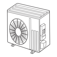
Illustrates and names external parts of the outdoor unit.
Details capacity, power, airflow, and refrigerant control parameters.
Lists unit dimensions, weight, piping sizes, and refrigerant charge.
Specifies guaranteed voltage and operating limits for power supply.
Outlines indoor/outdoor air conditions for performance tests.
Provides detailed measurements and installation space requirements for various models.
Shows the internal electrical connections for various models.
Illustrates the refrigerant flow and key components for different models.
Specifies max piping, height difference, and refrigerant charge calculation methods.
Lists cooling capacity and correction factors at various conditions.
Provides factors to adjust cooling and heating capacity based on piping length.
Details heating capacity at different indoor/outdoor temperatures.
Graphical representation of cooling capacity vs. temperature.
Graphical representation of heating capacity vs. temperature.
Shows condensing pressure variations based on temperatures.
Shows pressure variations during heating based on temperatures.
Lists key electrical and operational data for various models.
Illustrates how inverter frequency affects capacity and input.
Guides users on performing test run operations with fixed frequency.
Explains the control sequence for the outdoor fan motor and R.V. coil.
Details how sensors relate to specific actuators for protection and control.
Instructions for adjusting defrost settings and pre-heat control function.
Important safety warnings and general troubleshooting steps.
Visual guide to recall and operate the failure mode recall function.
Step-by-step process to diagnose outdoor unit specific failures.
Lists failure codes, symptoms, and corresponding remedies for outdoor units.
Links symptoms, LED indications, and remedies for system failures.
Specifies resistance values and checks for key parts like thermistors and compressor.
Diagnostic steps for inverter and compressor issues.
Procedures to test compressor winding, operation time, and start issues.
Guides for measuring thermistor resistance and verifying unit operation.
Steps to check R.V. coil and 4-way valve operation and voltage.
Procedure to test outdoor fan motor resistance and voltage output.
Verifies power supply, AC voltage, DC bus voltage, and LED status.
Guides for verifying LEV click, vibration, coil resistance, and voltage.
Steps to check fuse, motor connections, and LED blink codes on the inverter board.
Guides for detecting and correcting wiring issues and serial signal errors.
Verifies defrost heater, thermistors, and refrigerant circuit for proper function.
Steps to diagnose and mitigate electromagnetic interference with external devices.
Identifies test points and voltage measurements on the inverter board.
Step-by-step guide to remove the outer cabinet panels.
Instructions for disassembling and removing the inverter system components.
Procedure for detaching the reversing valve coil.
Steps to remove discharge, defrost, outdoor heat exchanger, and ambient thermistors.
Instructions for disassembling and removing the outdoor fan motor assembly.
Steps to detach and remove the compressor and its connected pipes.