Do you have a question about the Mitsubishi Electric NZ2GFSS2 32D S1 and is the answer not in the manual?
| Brand | Mitsubishi Electric |
|---|---|
| Model | NZ2GFSS2 32D S1 |
| Category | I/O Systems |
| Language | English |
Indicates hazardous conditions resulting in death or severe injury.
Indicates hazardous conditions resulting in minor injury or property damage.
Precautions for module power supply errors, communication failures, and output behavior.
Measures to maintain system security against cyberattacks.
Precautions for safe installation and handling of the module.
Warning about shutting off power before wiring to prevent electric shock.
Precautions for grounding, wiring, and preventing foreign matter entry.
Warning about touching terminals while power is on to prevent electric shock.
Precautions for disassembly, radio devices, static discharge, and handling.
States that certification does not guarantee freedom from malfunction or failure.
Details the specifications for DC input modules.
Details the specifications for transistor output modules.
Details the specifications for combined input/output modules.
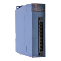
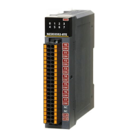
Identifies components and their functions for the main module.
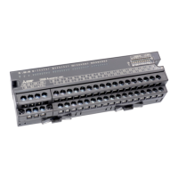
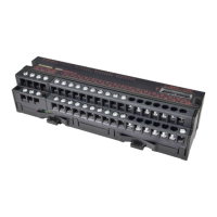
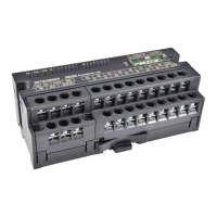
Identifies components and their functions for the extension module.
Details environmental, operational, and safety specifications.
Outlines the electrical, communication, and functional performance specs.
Lists available functions for different module models.
Steps for determining safety category, wiring, and network settings.
Procedures for mounting, wiring, unit testing, and parameter configuration.
Illustrates system configurations with main and extension modules.
Lists compatible hardware and software packages for the system.
Lists safety standards the product complies with.
Sets network and station numbers using switches and engineering tool.
Specifies environmental conditions and physical placement for installation.
Details the procedure for connecting extension modules to the main module.
Provides steps for securely mounting the module on a DIN rail.
Details wiring procedures for module power supply and FG terminals.
Explains the connection and disconnection procedures for Ethernet cables.
Details wiring procedures for external power supply and I/O signal terminals.
Configures network parameters like station numbers and data assurance.
Lists and explains module parameters configurable via engineering tool.
Manages safe input signals and wiring selection, including diagnostics.
Manages safe output signals, wiring selection, and diagnostics.
Covers functions for detecting input errors like discrepancy and dark tests.
Covers functions for detecting output errors like dark tests and read-back.
Details module protection mechanisms against overvoltage and overcurrent.
Controls access to the module and CPU via user authentication.
Configures module behavior upon external power supply voltage errors.
Lists functions enabled by connecting extension modules.
Explains how to use diagnostics for CC-Link IE networks.
Guides troubleshooting by interpreting the status of module LEDs.
Describes how to perform a unit test to check for hardware failures.
Provides solutions for common operational issues without explicit errors.
Lists common input/output circuit faults and their corrective actions.
Explains methods for checking and interpreting error codes.
Provides a comprehensive list of error codes, classifications, and causes.
Maps safety I/O signals to specific device numbers for different modules.
Details the names and device numbers of safety remote input/output signals.
Lists signals used for controlling and monitoring module functions.
Provides specific details on warning status, error status, and remote ready signals.
Lists the remote register areas used for safety communication.
Explains the specific output Y ON/OFF information and clear request registers.
Organizes buffer memory areas by type and access method.
Details specific parameter, monitoring, and error history areas.
Details precautions and standards for electromagnetic compatibility.
Procedures for installing modules within a conductive control panel for EMC compliance.
Details compliance with machinery safety directives and standards.
Details precautions and standards for electrical safety compliance.
How to check serial and function versions using the rating plate.
How to check serial and function versions using diagnostics software.
Provides external dimensions for main modules.
Provides external dimensions for extension modules.