EasyManua.ls Logo

Mitsubishi Electric PKFY-P06NLMU-E.TH User Manual

Mitsubishi Electric PKFY-P06NLMU-E.TH
38 pages
To Next Page IconTo Next Page
Page #1 background imageLoading...
Page #1 background image
TECHNICAL & SERVICE MANUAL
CONTENTS
1. SAFETY PRECAUTION
..........................
2
2. PARTS NAMES AND FUNCTIONS
........
4
3. SPECIFICATION
...................................
12
4. NOISE CRITERION CURVES
...............
15
5. OUTLINES AND DIMENSIONS
............
17
6. WIRING DIAGRAM
...............................
19
7. REFRIGERANT SYSTEM DIAGRAM
........
20
8. MICROPROCESSOR CONTROL
.........
20
9. TROUBLESHOOTING
..........................
27
10. DISASSEMBLY PROCEDURE
...........
35
Indoor unit
[Model Name] [Service Ref.]
INDOOR UNIT
R410A
Model name
indication
PARTS CATALOG (OCB715)
No. OCH715
March 2020
SPLIT-TYPE, HEAT PUMP AIR CONDITIONERS
PKFY-P04NLMU-E
PKFY-P04NLMU-E.TH
PKFY-P06NLMU-E
PKFY-P06NLMU-E.TH
PKFY-P08NLMU-E
PKFY-P08NLMU-E.TH
PKFY-P12NLMU-E
PKFY-P12NLMU-E.TH
PKFY-P15NLMU-E
PKFY-P15NLMU-E.TH
PKFY-P18NLMU-E
PKFY-P18NLMU-E.TH
Note:
• This manual describes
service data of the indoor
units only.

Table of Contents

Question and Answer IconNeed help?

Do you have a question about the Mitsubishi Electric PKFY-P06NLMU-E.TH and is the answer not in the manual?

Mitsubishi Electric PKFY-P06NLMU-E.TH Specifications

General IconGeneral
BrandMitsubishi Electric
ModelPKFY-P06NLMU-E.TH
CategoryAir Conditioner
LanguageEnglish

Summary

SAFETY PRECAUTION

Refrigerant R410A Cautions

Safety guidelines for using refrigerant R410A and related procedures.

Essential Service Tools for R410A

Lists and specifies tools required for servicing R410A refrigerant systems.

PARTS NAMES AND FUNCTIONS

Indoor Unit Component Identification

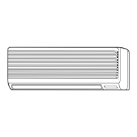
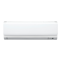
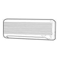
Identifies and describes the parts of the indoor unit.

Wired Remote Controller Functions

Details the functions supported by the wired remote controller.

Remote Controller Interface and Operation

Explains the remote controller display, buttons, and basic operation.

Remote Controller Display Information

Describes various icons and display modes on the remote controller.

Wireless Remote Controller Operation

Covers the interface, display, and operation of the wireless remote controller.

SPECIFICATIONS

General Unit Specifications

Provides detailed technical specifications for different indoor unit models.

Electrical Component Specifications

Lists electrical parts and their specifications used in the indoor units.

NOISE CRITERION CURVES

OUTLINES AND DIMENSIONS

WIRING DIAGRAM

REFRIGERANT SYSTEM DIAGRAM

MICROPROCESSOR CONTROL

Cool Operation Control

Details the control logic and operation for the cooling mode.

Operation Mode Control Details

Explains control functions for temperature, fan, drain pump, and vane.

Dry Operation Control

Describes the control logic and operation for the dry mode.

Fan Operation Control

Details the control logic and operation for the fan-only mode.

Heat Operation Control

Describes the control logic and operation for the heating mode.

Auto Operation Control

Explains automatic switching between cooling and heating modes.

Unit Stopped Control Mode

Describes control functions when the unit is in a stopped state.

TROUBLESHOOTING

Part Checking Procedures

Guides on how to check the resistance and functionality of various parts.

Thermistor and Linear Expansion Valve Characteristics

Provides characteristic graphs and specifications for thermistors and LEV.

Fan Motor and Connection Troubleshooting

Details troubleshooting steps for DC fan motors and wiring connections.

Function of DIP Switches

Explains the functions and settings of various DIP switches.

Test Point Diagram Analysis

Illustrates test points on the indoor controller board and PCBs.

DISASSEMBLY PROCEDURE

Removing Panels and Electrical Boxes

Step-by-step guide for removing the unit's front panel and electrical covers.

Removing Internal Boards and Motors

Instructions for removing controller boards, LED boards, and vane motors.

Removing Fan, Thermistors, and Heat Exchanger

Procedures for removing the fan motor, thermistors, and heat exchanger.

Related product manuals