Do you have a question about the Mitsubishi Electric PKFY-P32VLM-E.TH and is the answer not in the manual?
| Brand | Mitsubishi Electric |
|---|---|
| Model | PKFY-P32VLM-E.TH |
| Category | Air Conditioner |
| Language | English |
Safety guidelines for handling R410A refrigerant, piping, and tools.
Proper use of vacuum pumps and specific tools for R410A refrigerant systems.
Important precautions to follow during maintenance and service procedures.
Technical data for different indoor unit models, including power, capacity, and dimensions.
Specifications for electrical parts like thermistors, motors, and fuses used in the units.
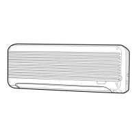
Diagrams showing physical dimensions and installation clearances for specific unit series.
Diagrams showing physical dimensions and installation clearances for specific unit series.
Schematic showing the electrical connections and components within the indoor unit.
Diagram illustrating the refrigerant flow and key components of the system.
Methods for checking thermistors, motors, and other components for faults.
Step-by-step guide for diagnosing and resolving issues with the DC fan motor.
Troubleshooting common problems related to the linear expansion valve operation.
Diagram showing key test points on the indoor controller board for diagnosis.
Step-by-step instructions for removing the front panel and corner box of the indoor unit.
Guidance on how to safely remove the electrical box and its components.