Do you have a question about the Mitsubishi Electric PU(H)Y-P250YGM-A and is the answer not in the manual?
| Cooling Capacity | 25.0 kW |
|---|---|
| Heating Capacity | 28.0 kW |
| Refrigerant | R410A |
| Operating Temperature (Cooling) | -5°C to 46°C |
| Power Supply | 380-415V, 50Hz |
Essential safety instructions for installation, operation, and maintenance to prevent injury or damage.
Precautions for handling units with R410A refrigerant, including piping and tool usage.
Instructions on where not to install, environmental considerations, and special locations like hospitals.
Guidelines for proper grounding, electrical wiring, breakers, and unit handling during installation.
Essential checks and procedures to perform before initiating the unit's test run.
Essential guidelines, tools, materials, and procedures before performing any service tasks.
Outlines restrictions on system configuration, cable types, settings, and pipe lengths.
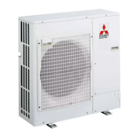
Details the components, refrigerant circuits, control boxes, and circuit boards of outdoor units.
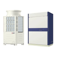
Describes indoor unit external dimensions, internal structure, control boxes, and circuit boards.
Provides detailed electrical wiring diagrams for both outdoor and indoor units.
Illustrates refrigerant circuits and explains the principal parts and their functions.
Explains dipswitch functions, unit control, operation modes, and flow charts.
Details compressor frequency control, defrost operation, and refrigerant recovery control.
Explains emergency operation, power failures, and test run procedures.
Comprehensive list of error codes, their definitions, causes, and troubleshooting steps.
Detailed troubleshooting for specific components like sensors, valves, fans, and inverter circuits.
Troubleshooting for remote controller malfunctions and transmission line/noise issues.
Explains how to read LED displays on the service monitor and interpret table data.