EasyManua.ls Logo

Mitsubishi Electric PUZ-WM50VHA User Manual

Mitsubishi Electric PUZ-WM50VHA
86 pages
To Next Page IconTo Next Page
Page #1 background imageLoading...
Page #1 background image
SERVICE MANUAL
No. OCH727
R32
March 2020
PARTS CATALOG (OCB727)
<Outdoor unit>
[Model Name]
PUZ-WM50VHA
PUZ-WM60VAA
PUZ-WM85VAA
PUZ-WM85YAA
PUZ-WM112VAA
PUZ-WM112YAA
Salt proof model
PUZ-WM50VHA-BS
PUZ-WM60VAA-BS
PUZ-WM85VAA-BS
PUZ-WM85YAA-BS
PUZ-WM112VAA-BS
PUZ-WM112YAA-BS
CONTENTS
1. REFERENCE MANUAL ································ 2
2. SAFETY PRECAUTION ······························· 3
3. SPECIFICATIONS ······································ 10
4. DATA ··························································· 12
5. OUTLINES AND DIMENSIONS·················· 13
6. WIRING DIAGRAM ····································· 15
7. WIRING SPECIFICATIONS ························ 18
8. REFRIGERANT SYSTEM DIAGRAM ········ 19
9. TROUBLESHOOTING ································ 22
10.
MONITORING THE OPERATION DATA BY THE REMOTE CONTROLLER
···· 60
11. DISASSEMBLY PROCEDURE ··················· 66
Note:
• This manual describes
service data of the outdoor
units only.
AIR TO WATER HEAT PUMP UNITS
[Service Ref.]
PUZ-WM50VHA.UK
PUZ-WM60VAA.UK
PUZ-WM85VAA.UK
PUZ-WM85YAA.UK
PUZ-WM112VAA.UK
PUZ-WM112YAA.UK
PUZ-WM50VHA-BS.UK
PUZ-WM60VAA-BS.UK
PUZ-WM85VAA-BS.UK
PUZ-WM85YAA-BS.UK
PUZ-WM112VAA-BS.UK
PUZ-WM112YAA-BS.UK
PUZ-WM50VHA.UK

Table of Contents

Question and Answer IconNeed help?

Do you have a question about the Mitsubishi Electric PUZ-WM50VHA and is the answer not in the manual?

Mitsubishi Electric PUZ-WM50VHA Specifications

General IconGeneral
Cooling Capacity5.0 kW
Heating Capacity6.0 kW
RefrigerantR410A
TypeHeat Pump
Power Supply220-240 V
Voltage (V)220-240 V
Phase1
Operating Temperature Range (Cooling)-10°C to 46°C
Operating Temperature Range (Heating)-20 to 24 °C

Summary

Reference Manual

1-1. FOR AIR TO WATER SYSTEM

Details the reference information for air to water systems.

Safety Precaution

2-1. ALWAYS OBSERVE FOR SAFETY

Essential safety guidelines to always follow during operation and maintenance.

2-2. CAUTIONS RELATED TO NEW REFRIGERANT

Specific precautions for handling new refrigerants, particularly R32.

Warning for service

Important warnings and instructions for service personnel regarding refrigerant and unit safety.

Cautions for service

General cautions and procedures to follow during service operations.

Refrigerant charge

Procedures and considerations for charging refrigerant into the system.

Cautions for unit using R32 refrigerant

Detailed safety precautions specifically for units utilizing R32 refrigerant.

Specifications

3-1. SPECIFICATIONS

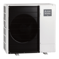
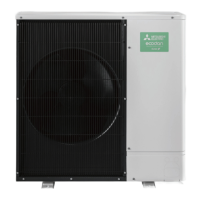
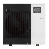
Technical specifications of the outdoor units, including power, dimensions, and components.

Wiring Diagram

PUZ-WM50VHA.UK PUZ-WM50VHA-BS.UK

Wiring diagram for PUZ-WM50VHA and PUZ-WM50VHA-BS models.

Wiring Specifications

Refrigerant System Diagram

PUZ-WM50VHA.UK PUZ-WM50VHA-BS.UK

Refrigerant circuit diagram for PUZ-WM50VHA and PUZ-WM50VHA-BS models.

PUZ-WM60VAA.UK PUZ-WM60VAA-BS.UK PUZ-WM85VAA.UK PUZ-WM85VAA-BS.UK

Refrigerant circuit diagrams for PUZ-WM60VAA and PUZ-WM85VAA models.

PUZ-WM85YAA.UK PUZ-WM112YAA.UK PUZ-WM112YAA-BS.UK

Refrigerant circuit diagrams for PUZ-WM85YAA and PUZ-WM112YAA models.

Troubleshooting

9-1. TROUBLESHOOTING

General guide to troubleshooting based on self-diagnosis codes and unit conditions.

9-2. SELF-DIAGNOSIS ACTION TABLE

Detailed table for diagnosing and taking action based on detected abnormalities.

9-3. TROUBLESHOOTING OF PROBLEMS

Guidance for troubleshooting common operational problems and their solutions.

9-4. HOW TO CHECK THE PARTS

Procedures for checking the resistance and condition of various unit components.

9-5. HOW TO CHECK THE COMPONENTS

Methods for checking specific components like pressure sensors and their circuits.

Disassembly Procedure

13. Removing the compressor (MC)

Detailed procedure for removing the main compressor unit.

Related product manuals