EasyManua.ls Logo

Mitsubishi Electric PVFY-P12 User Manual

Mitsubishi Electric PVFY-P12
46 pages
To Next Page IconTo Next Page
Page #1 background imageLoading...
Page #1 background image
SPLIT-TYPE, HEAT PUMP AIR CONDITIONERS
SERVICE MANUAL
Model name
<Indoor unit>
Model name
<Indoor unit>
Series PVA
2015
PVA-A30AA4
PVA-A36AA4
PVA-A42AA4
INDOOR UNIT
Air-Conditioners
PVFY-P12, 18, 24, 30, 36, 48, 54NAMU-E1
Multi-Position Air Handler
SPLIT-TYPE, HEAT PUMP AIR CONDITIONERS
SERVICE MANUAL
Model name
<Indoor unit>
Model name
<Indoor unit>
Series PVA
2015
PVA-A30AA4
PVA-A36AA4
PVA-A42AA4
INDOOR UNIT
Question and Answer IconNeed help?

Do you have a question about the Mitsubishi Electric PVFY-P12 and is the answer not in the manual?

Mitsubishi Electric PVFY-P12 Specifications

General IconGeneral
BrandMitsubishi Electric
ModelPVFY-P12
CategoryAir Handlers
LanguageEnglish

Summary

Safety Precautions for Installation and Operation

General Safety Information and Symbols

Explains safety symbols and general warnings for safe operation.

R410A Refrigerant Handling Precautions

Specific guidelines for safe handling and use of R410A refrigerant.

Unit Features and Capacities

Model Capacities Overview

Details cooling and heating capacities for different unit models.

Part Names and Functions

Indoor Unit Component Identification

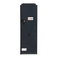
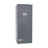
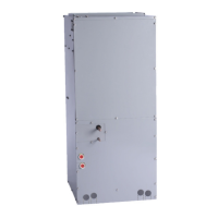
Illustrates and names the key parts of the indoor unit.

Remote Controller Operation

Controller Buttons and Display Icons

Explains remote controller buttons, functions, and display icons.

Unit Specifications

General Technical Specifications

Provides comprehensive technical data including electrical and physical specs.

Electrical Component Specifications

Lists specifications for specific electrical components within the unit.

Unit Design and Diagrams

Indoor Unit Dimensions and Layout

Illustrates physical dimensions, layout, and installation clearances.

Wiring Diagram and Symbols

Details electrical wiring connections and explains associated symbols.

Refrigerant System Diagram

Visual representation of the unit's refrigerant circuit and components.

Operation and Control Modes

Microprocessor Control Modes

Explains operation in Cool, Dry, Fan, Heat, and Auto modes.

Heater Control Settings and Operation

Details heater control logic, DIP switch settings, and operation examples.

Humidifier and Fan Control

Covers humidifier control specifications and fan indication settings.

Troubleshooting and Maintenance

General Troubleshooting Methods

Provides basic methods for checking unit components and diagnosing faults.

Component-Specific Checks

Detailed checks for thermistors, fan motors, and linear expansion valves (LEV).

Disassembly Procedures

Step-by-step instructions for safely disassembling unit components.

Configuration and Settings

Address Switch Settings

Guide to setting unit addresses using rotary switches on the control board.

Dipswitch Settings for Unit Configuration

Explains how to configure unit functions using various dipswitches.

Related product manuals