2
SYSTEM CONFIGURATION
2.1 System Configuration
2.1.4 System configuration overview
2 - 9
1
OVERVIEW
2
SYSTEM
CONFIGURATION
3
SPECIFICATIONS
4
FUNCTIONS
5
ACCESS VIA NETWORK
MODULES
6
PREPARATORY
PROCEDURES AND
SETTING
7
I/O NUMBER
ASSIGNMENT
8
MEMORIES AND FILES
2.1.4 System configuration overview
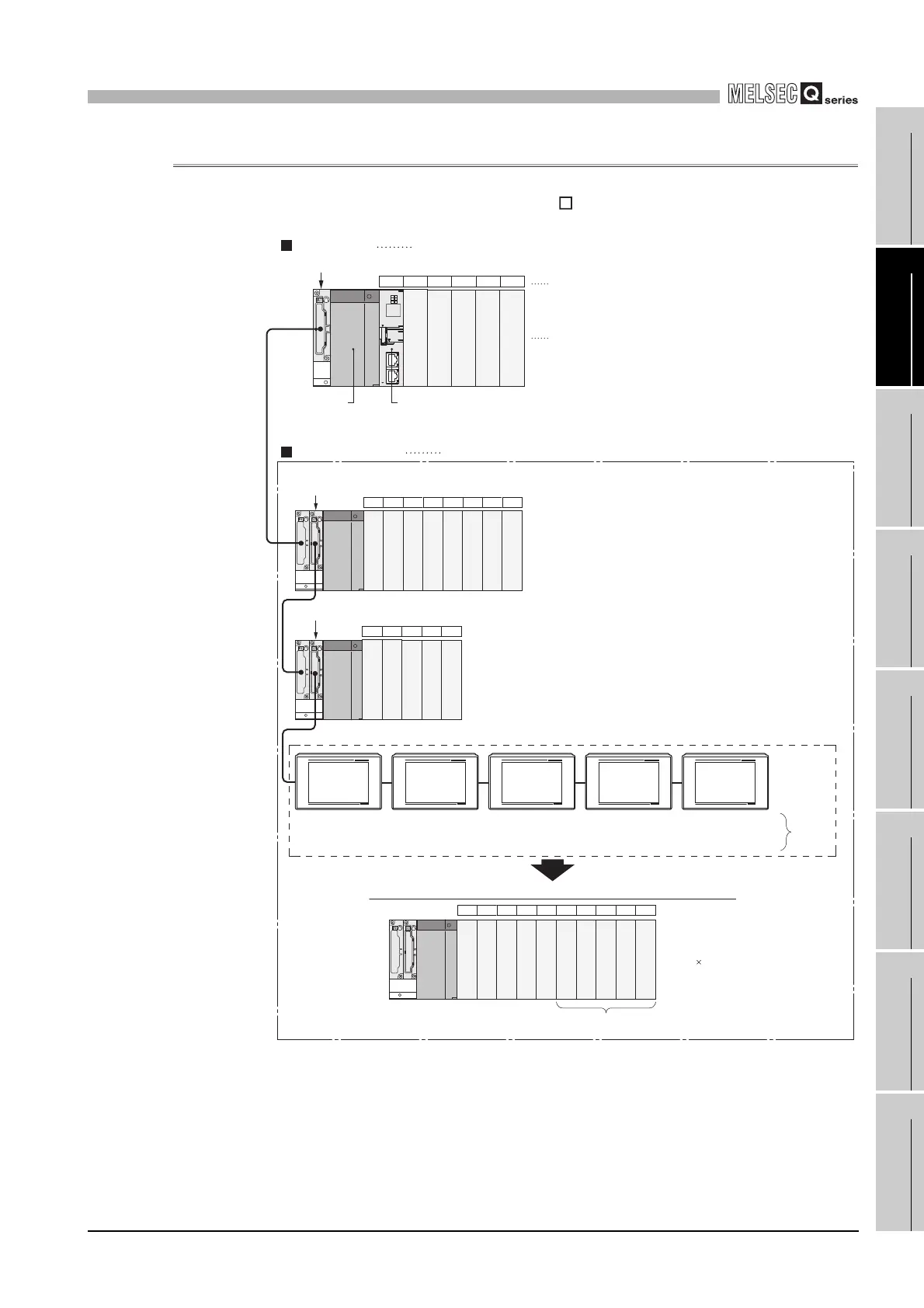
(1) When using the main base unit (Q3 B)
Figure 2.8 Configuration example of a system using a main base unit
C Controller module
Q35B (exclusive 5 slots)
Q68B (exclusive 8 slots)
Q65B (exclusive 5 slots)
00 to 0F
10 to 1F
20 to 2F
30 to 3F
40 to 4F
50 to 5F
60 to 6F
70 to 7F
80 to 8F
90 to 9F
A0 to AF
B0 to BF
C0 to CF
D0 to DF
E0 to EF
F0 to FF
100 to 10F
110 to 11F
CPU 0 1 2 3 4
5 6 7 8 9 101112
13 14 15 16 17
Q series
power supply
module
Number of
Ext.Bases: 3
Slot No.: 0
The extension base image for GOT connection by C Controller module side
120 to 12F
130 to 13F
140 to 14F
150 to 15F
160 to 16F
18 19 20 21 22 23 24 25 26 27
1) 2) 3) 4) 5)
1) 2) 3) 4) 5)
Number of
Ext.Bases: 3
Slot No.: 1
Number of
Ext.Bases: 3
Slot No.: 2
Number of
Ext.Bases: 3
Slot No.: 3
Number of
Ext.Bases: 3
Slot No.: 4
Setting
by GOT
Sets data as empty in "I/O assignment setting" of
C Controller setting utility.
Slot No.
I/O No.
GOT (extension base number: 3)
16 points exclusive 10 slots
Main base unit A 16-point module is mounted on each slot
Extension base unit A 16-point module is mounted on each slot
 Loading...


