Do you have a question about the Mitsubishi Electric Q81BD-J61BT11 and is the answer not in the manual?
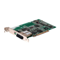
| Model | Q81BD-J61BT11 |
|---|---|
| Manufacturer | Mitsubishi Electric |
| Category | Computer Hardware |
| Series | Q Series |
| Communication Protocol | CC-Link |
| Communication Standard | CC-Link Ver.1.10 |
| Ports | 1 |
| Transmission Speed | 156 kbps to 10 Mbps |
| Current Consumption | 0.5A |
| Weight | 0.2 kg |
| Type | Interface Module |
| Product Type | Communication Module |
| Compatible Series | Q Series PLC |
| Data Rate | 10 Mbps |
| Number of Stations | 64 |
| Power Supply | DC |
| Power Supply Voltage | 5 VDC |
| Network Type | CC-Link |
Guidelines for safe design and implementation of the system.
Safety guidelines for connecting cables and wiring the system.
Specifies the required hardware and software environment for operation.
Details the technical performance characteristics and data of the board.
Explains fundamental communication capabilities of the CC-Link Ver.2 board.
Details features designed to enhance the system's stability and fault tolerance.
Covers the functions for performing data transmission at arbitrary timings.
Outlines the necessary steps before operating the CC-Link Ver.2 board.
Identifies and explains the names and settings of CC-Link Ver.2 board components.
Details the precautions and steps for installing the CC-Link Ver.2 board.
Explains the cable wiring procedures and precautions for the CC-Link system.
Guides on how to set station numbers for various devices in the system.
Explains how to configure transmission rate and operation modes.
Describes how to perform tests to verify the CC-Link Ver.2 board and cables.
Step-by-step guide for installing the CC-Link Ver.2 software.
Details on how to operate the CC-Link Ver.2 utility software.
Steps for starting and checking the data link status.
Steps to start and check the data link status.
Steps to start and check the data link status.
Solutions for issues during software installation or uninstallation.
Steps to resolve startup or system downtime issues.
Addresses problems related to the hardware board and its drivers.
Specific checks and procedures for CC-Link system issues.