3 - 1 3 - 1
MELSEC-Q
3 SPECIFICATIONS
3 SPECIFICATIONS
The following describes the performance specifications, I/O signals for the
programmable controller CPU and buffer memory specifications of the QD62(E/D).
For the general specifications of the QD62(E/D), see the User's Manual for the CPU
module used.
3.1 Performance Specifications
The following describes the performance specifications of the QD62(E/D):
(1) QD62 (DC input sinking output type) performance specifications
Model name
Item
QD62
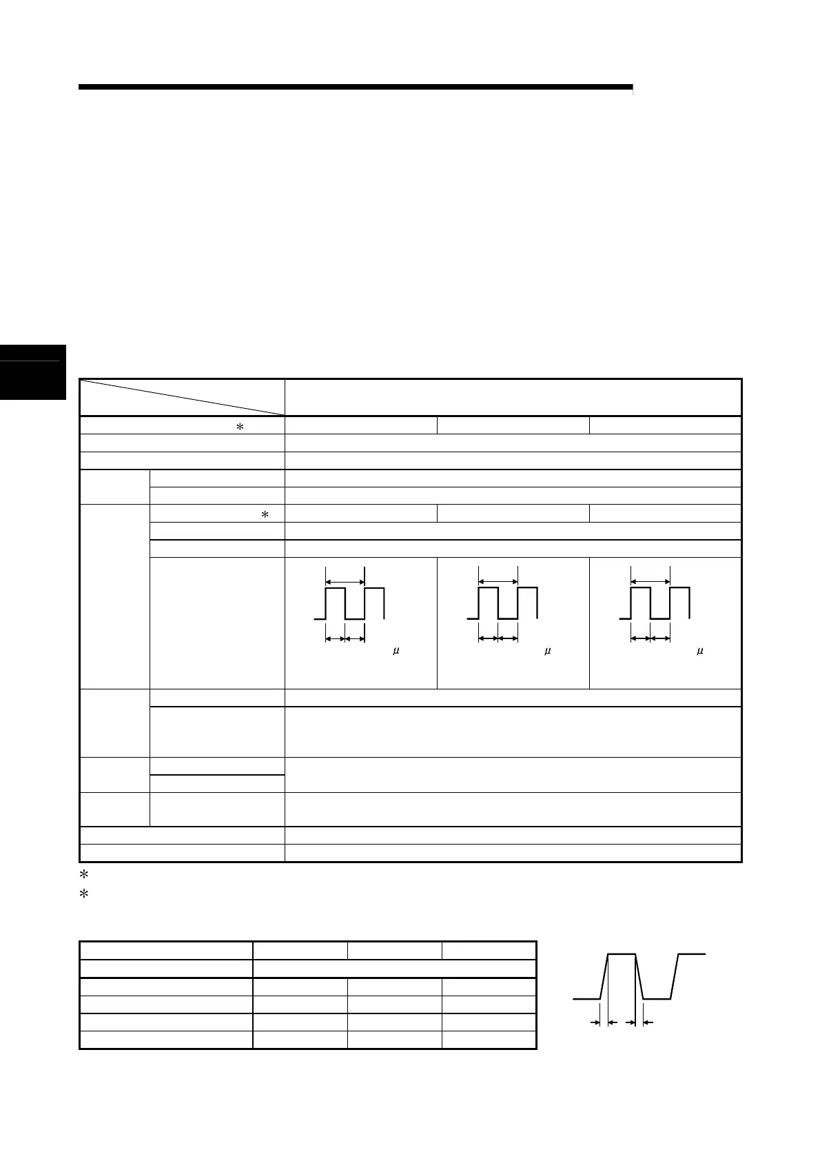
Counting speed switch settings 1 200 k (100 k to 200 kPPS) 100 k (10 k to 100 kPPS) 10 k (10 kPPS or less)
I/O occupied points 16 points (I/O assignment: Intelligent 16 points)
Number of channels 2 channels
Phase 1-phase input, 2-phase input Count input
signal
Signal level (
φ
A,
φ
B) 5/12/24 V DC 2 to 5 mA
Counting speed (max) 2 200 kPPS 100 kPPS 10 kPPS
Counting range 32-bit signed binary values (–2147483648 to 2147483647)
Model UP/DOWN Preset counter + Ring counter function
Counter
Minimum count pulse
width (Duty ratio 50 %)
2.5 2.5
5
(Unit: s)
(Min. phase differential for
2-phase input: 1.25 μ s)
5 5
10
(Unit: s)
(Min. phase differential for
2-phase input: 2.5 μ s)
50 50
100
(Unit: s)
(Min. phase differential for
2-phase input: 25 μ s)
Comparison range 32-bit signed binary values
Coincidence
output
Comparison result
Set value < Count value
Set value = Count value
Set value > Count value
Preset External
input
Function start
5/12/24 V DC
2 to 5 mA
External
output
Coincidence output
Transistor (sinking type) output: 2 points/channel
12/24 V DC 0.5 A/point 2 A/common
5V DC internal current consumption 0.30 A
Weight 0.11 kg
1: The counting speed switch settings can be set using the intelligent function module switch.
2: Counting speed is affected by pulse rise and fall time. Possible counting speeds are shown in the following
table. Note that if a pulse that has a large rise and/or fall time is counted, a miscount may occur.
Counting speed switch settings 200 k 100 k 10 k
Rise/fall time Both 1 and 2 phase input
t = 1.25 μ s or less 200 kPPS 100 kPPS 10 kPPS
t = 2.5 μ s or less 100 kPPS 100 kPPS 10 kPPS
t = 25 μ s or less
—
10 kPPS 10 kPPS
t = 500 μ s
— —
500 PPS
tt
3
 Loading...

