4 - 6 4 - 6
MELSEC-Q
4 SETUP AND PROCEDURE BEFORE STARTING THE OPERATION
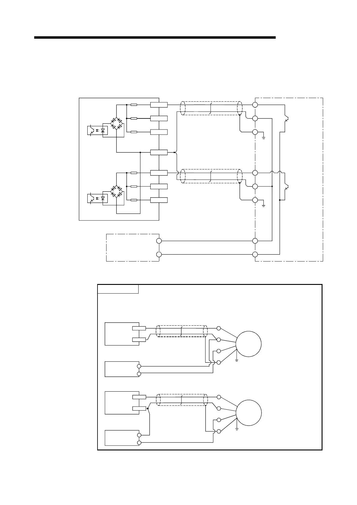
4.4.2 Wiring example of a module and an encoder
(1) Wiring example with an open collector output type encoder (24 V DC)
A20 (A13)
24 V
B20(B13)
12 V
A19(A12)
5 V
B19(B12)
ABCOM
Phase A
Shield
Shielded twisted pair cable
OUT
E
+24 V
EncoderQD62,QD62E
A18(A11)
24 V
B18(B11)
12 V
A17(A10)
5 V
Phase B
OUT
E
+24 V
0 V
+24 V
0 V
24 V DC
External
power
supply
Shielded twisted pair cable
Shield
The number inside the ( ) indicates the terminal number for channel 2.
POINT
When wiring the QD62, QD62E, and the encoder, separate the power supply cable
and signal cable. The following diagram shows an example.
[Wiring example]
24 V
ABCOMPhase
A
QD62(E)
OUT
0 V
24 V DC
External
power
supply
Encoder
+24 V
0 V
E
[Incorrect wiring example]
OUT
Encoder
+24 V
0 V
E
24 V
ABCOMPhase
A
QD62(E)
0 V
24 V DC
External
power
supply
The current flows
through the shielded
twisted pair cables in
the same direction, so
there is no cancelling
effect.
This makes it more
prone to electromagnetic
induction.
 Loading...

