Do you have a question about the Mitsubishi Electric SLZ-KF18NA1 and is the answer not in the manual?
| Refrigerant | R410A |
|---|---|
| Cooling Capacity | 5.0 kW |
| Energy Efficiency Ratio (EER) | 3.6 COP |
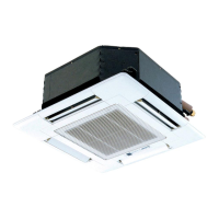
| Indoor Unit Dimensions (W x H x D) | 800 x 295 x 223 mm |
| Weight | 10 kg |
| Power Supply | 1-Phase |
| Coefficient of Performance (COP) | 3.6 |
| Noise Level (Indoor Unit) | 24 dB(A) |
| Indoor Unit Dimensions (HxWxD) | 295 x 800 x 223 mm |
| Indoor Unit Weight | 10 kg |
Emphasizes disconnecting all supply circuits before accessing terminals for safety.
Prohibits unauthorized unit modifications and mandates complete refrigerant recovery.
Guides actions based on reoccurring troubles and check code status.
Explains diagnosing malfunctions using remote controller beep and blink patterns.
Lists specific error codes for the indoor unit, their symptoms, and remarks.
Details error codes originating from units other than the indoor unit.
Troubleshooting steps for drain pump lock protection and fan motor errors.
Countermeasures for freezing/overheating protection and pipe temperature anomalies.
Addresses TH5 issues and refrigerant circuit abnormalities, including 4-way valve checks.
Troubleshooting steps for remote controller transmission and signal receiving errors.
Covers troubleshooting for forced compressor stops caused by water leakage abnormalities.
Explains how to interpret LED2 status on the indoor controller board for troubleshooting.
Provides methods for checking the resistance of thermistors and the vane motor for troubleshooting.
Describes how to view error codes, units, and contact information, and how to reset errors.
Explains how to view error history records and how to delete them from the controller.
Guides on performing self-diagnosis for indoor units using the PAR-41MAA controller.
Details steps to perform a self-check for indoor units using the PAR-SL101A-E remote controller.
Explains how to check remote controller performance and diagnose issues like transmission line noise.