-
99
-
CAUTION
¡ Taps should not be used under static pressure outside the unit mentioned above. Dew
condensation may occur with the unit and wet the ceiling or furniture.
¡ Do not use under static pressure outside the unit of 50Pa or less. Water drops may be blown
from the diffuser outlet of the unit and wet the ceiling or furniture.
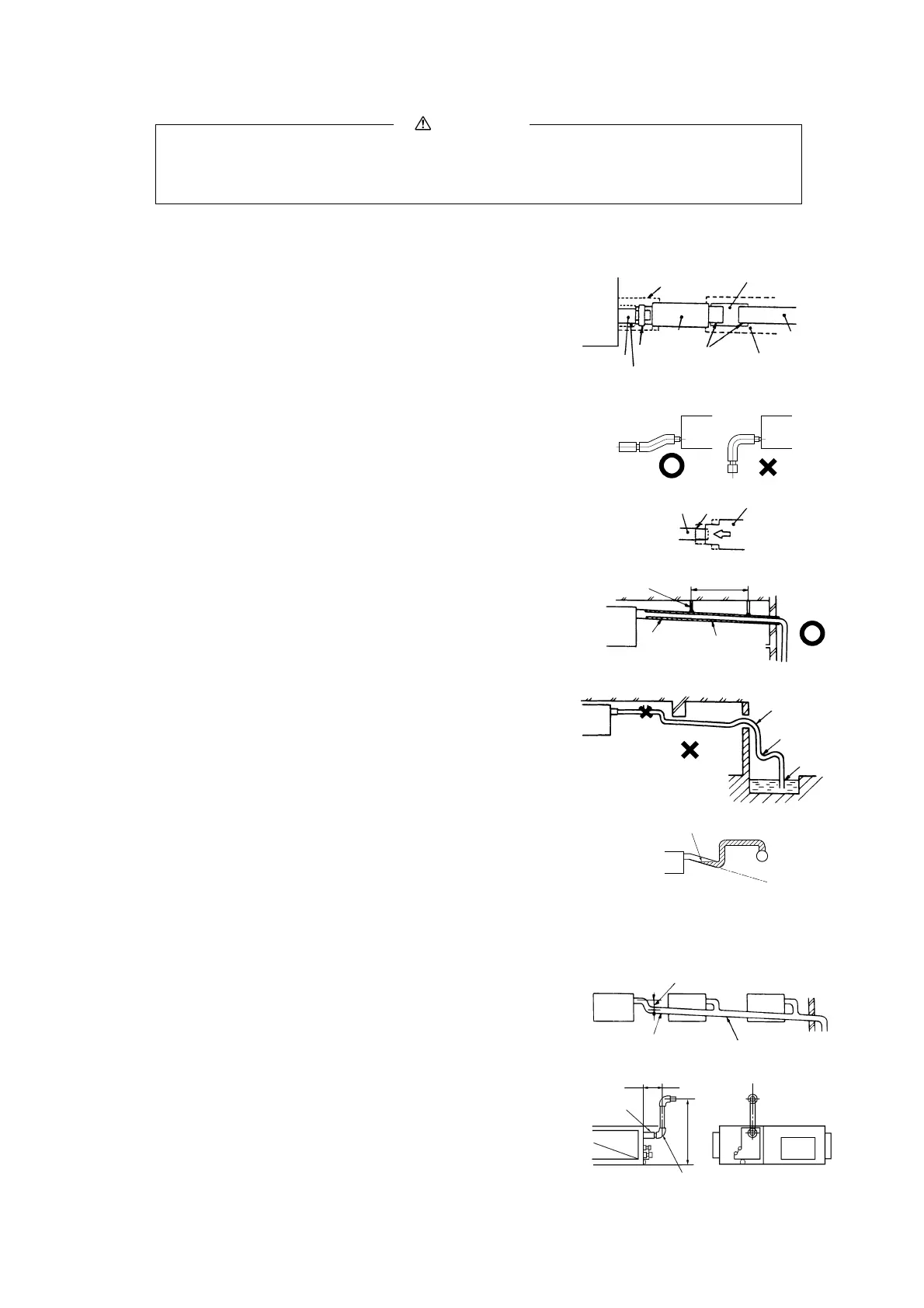
Drain socket
Clamp
(accessory)
No adhesive allowed
Pipe cover (large)
[for insuation]
(accessory)
Joint for VP25
(not included)
Drain hose
(accessory)
Indoor
unit
Adhesion
Pipe cover (small)
[for insuation]
(accessory)
Pipe cover
[for insuation]
(not included)
VP25
(not included)
Drain hose
Stepped
part
Drain socket
1.5 m ~ 2 m
Suspension
bolts
Desceding slope
greater than 1/100
Insulation
material
No bump
Air vent
No trap
Not
touching
the water
As wide as possible
(about 100 mm)
VP30
Desceding slope
greater than 1/100
1) Glue the drain hose supplied as an accessory and a VP-25 joint before
lifting the unit.
2) The drain hose is to provide a buffer to absorb a slight dislocation of the
unit or the drain piping during installation work. If it si subject to abuse
such as being bent or pulled deliberately, it may break, which will result
in a water leak.
3) Care must be taken so as not to allow an adhesive to run into the drain
hose. When it is hardened, it can cause a breakage of a flexible part, if the
flexible part receives stress.
4) Use VP-25 general-purpose hard PVC pipes for drain piping.
5) Insert the drain hose supplied as an accessory (soft PVC end) to the stepped
part of the unit’s drain socket and then fasten it with the clamp also sup-
plied as an accessory.
6) Adhesive must not be used.
a) Glue a VP-25 joint (to be procured locally) to joint it with the drain
hose (hard PVC end) and then glue a VP-25 (to be procured locally)
to the joint.
b) Give the drain piping a descending grade (1/50-1/100) and never cre-
ate a bump to go over or a trap.
c) In connecting drain pipes, care must be taken so as not to apply force
to the unit side piping and fix the pipe at a point as close to the unit as
possible.
d) Do not create an air vent under any circumstances.
e) When drain piping is implemented for more than one unit, provide a
collecting main about 100 mm below the units’ drain outlets from
which it collects drain. Use a VP-30 or larger pipe for a collecting
main.
f) Do not fail to provide heat insulation at the following two points be-
cause they can cause dew condensation and a resultant water leak.
7) Drain socket
After a drain test is completed, apply a pipe cover (small: accessory)
onto the drain socket, cover the pipe cover (small), the clamp and part of
the drain hose with a pipe cover (large: accessory) and wrap it with a tape
completely without leaving any gaps.
(Cut pipe covers into appropriate shapes)
8) Hard PVC pipes laid indoor
a) Since a drain pipe outlet can be raised up to 700 mm from the ceil-
ing, use elbows, etc. to install drain pipes, it there are obstacles pre-
venting normal drain pipe arrangement. When the drain pipe is raised
at a point far from a unit, it can cause an overflow due to a back flow
of drain upon stoppage, so arrange piping to keep the dimensions
specified in the illustration shown on the left.
b) Install the drain pipe outlet where no odor is likely to be generated.
c) Do not lead the drain pipe into a ditch where the generation of harm-
ful gas such as sulfuric gas or flammable gas is expected. A failure to
observe this instruction may cause such harmful or flammable gas to
flow into the room.
(d) Drain Piping
Trapped air will
generate noises.
295 ~ 325 mm
Drain hose
Right overhead
Joint for VP25 (not included)
Maximum local
drain up dimension
600 mm
 Loading...