Do you have a question about the Mitsubishi Heavy Industries SC-BIKN-E and is the answer not in the manual?
Details models compatible with the interface kit.
Lists devices that can be connected to the interface kit.
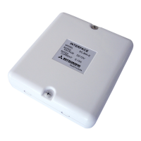
Provides physical dimensions of the interface kit.
Illustrates the layout of components on the interface kit's circuit board.
Describes the system configuration using a wired remote control.
Explains how to control multiple units with a single remote.
Details the setup for remote operation of air conditioning units.
Lists all accessories provided with the interface kit for installation.
Important safety guidelines and warnings to observe during installation.
Step-by-step guide for connecting the interface kit to the indoor unit's connection cable.
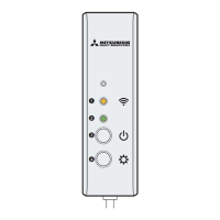
Identifies and describes the key parts of the interface kit.
Instructions for mounting the interface kit directly onto a flat wall surface.
Procedure for recessing the interface kit into a wall, including electrical box integration.
Steps for attaching the interface kit using a dedicated mounting bracket.
Key checks to perform after installation to ensure proper connection and cable compliance.
How to connect an external remote control unit to the CNT terminal.
Details wiring and DIP switch settings for connecting the Super Link E board.
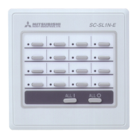
Explains controlling multiple units with a single wired remote control.
Configuration for using two wired remote controls as master and slave.
Procedure to adjust the temperature setting range for the wired remote control.
Guidelines for installing and wiring the wired remote control unit.
How multiple units can be controlled by a single wired remote control.
Setting up master and slave configurations for dual wired remote controls.
Procedure to modify the temperature setting range for parallel wireless/wired control.
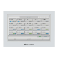
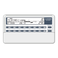
Detailed explanation of the wired remote control's LCD display and button functions.
Criteria for choosing an appropriate installation location for the wired remote control.
Steps for installing the remote control, covering both embedded and exposed cord methods.
Specifics on wiring requirements, cable types, and lengths for the wired remote control.
Automatic initial function settings for typical operation of remote and indoor units.
Step-by-step guide on how to set various functions using the remote control.
How to reset function settings to their factory defaults.
List and description of configurable functions for the remote control unit itself.
Configuration options for fan speed, filter indicator, and other unit-specific settings.
Settings for louver position, external input signals, and emergency stop functions.
Adjustments for temperature offset, fan control during heating, and frost prevention.
Guide to selecting and setting functions for the remote control unit.
Process for selecting and setting functions for individual indoor units or all units.
Steps to confirm and finalize function settings, and how to check current settings.
Defines adjustable ranges for upper and lower temperature limits based on operation mode.
Detailed steps to change the upper and lower temperature limits via the remote control.
Lists accessories for the Super Link adapter and its primary function for central control.
Explains control switches on the SL E board and outlines basic connection diagrams.
Instructions for mounting the SL E board in its metal box and securing wiring.
Guidelines for selecting an optimal installation location for the adapter, considering environmental factors.
Interpretation of LED indicators on the SL E board for communication and error status.
How DIP switch SW2-3 controls operation mode between permission and prohibition.
How CnT input signals manage operation permission or prohibition based on SW2-1 settings.
Describes output signals from the interface kit for operation, heating, compressor, and malfunctions.
How level input signals via the CnT connector control unit operation (ON/OFF).
How pulse input signals via the CnT connector control unit operation (ON/OFF).
| Brand | Mitsubishi Heavy Industries |
|---|---|
| Model | SC-BIKN-E |
| Category | Control Systems |
| Language | English |