and lower parts touch
to
the
spring seat and
act
to
reduce the control spring
force
by
torque spring force.
Stop
lever, which
is
installed
to
the upper parts of governor housing, pull back
the
control rack
to
the
position
"stop".
Stop lever shaft
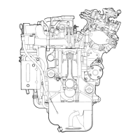
Fig.
3·28
Start
spring
Floating
lever
Camshaft bushing
Mechanism
of
RUV governor
Torque spring
Control spring
Supporting point B
Slip
disk Spring
seat
Angleich spring
Governor sleeve
Flyweight
Full load stopper
Supporting lever
Stopper
Stopper
bolt Supporting point A
Fig. 3-29 RUV governor, movement
of
idling
Oil inlet
Floatiag lever
Bearing bushing
3) Fig.
3·29
shows
the
situation of idling. Flyweight, though it
is
lower speed,
expand
to
the outside by centrifugal force, overcome weak spring force and
push
the
governor sleeve
to
the
right hand with spring lever.
Therefore floating lever's supporting point (B), which touch
to
governor sleeve,
-
32-
 Loading...