EasyManua.ls Logo

Mitsubishi DY-1MU3R45-T-2 User Manual

Mitsubishi DY-1MU3R45-T-2
31 pages
To Next Page IconTo Next Page
Page #1 background imageLoading...
Page #1 background image
SERVICE MANUAL
MITSUBISHI ELECTRIC CORP. SANDA WORKS
Your company internal use only.
DY-1MU3R45-T,-2
Copyright (C) Mitsubishi Electric Corporation.
SE046913053E Ver.pptx14E
MITSUBISHI MOTORS
AM/FM-ST ELECTRONIC TUNING RADIO, CD PLAYER
2014 May.
Model : DY-1MU3R45-T
DY-1MU3R45-T-2
MELCO Code : 34U284, 34W880
PART No. : 8701A405, 8701A405
FEATURES ........................................................................ 2,3
SPECIFICATIONS ................................................................ 4
OPERATION ......................................................................... 5
CONNECTORS .................................................................... 6
SYSTEM CONFIGURATION ................................................ 7
BLOCK DIAGRAM ................................................................ 8
DISASSEMBLING PROCEDURES ................................ 9~15
PARTS LIST ................................................................... 16,17
ELECTRICAL PARTS LIST ........................................... 18~24
PARTS LAYOUT ON PRINTED CIRCUIT BOARD ........ 25,26
SCHEMATIC DIAGRAM
PCB-MAIN ..................................................................... 27
VOLTAGE ..................................................................... 28~30
WAVEFORM ....................................................................... 31
CONTENTS
Question and Answer IconNeed help?

Do you have a question about the Mitsubishi DY-1MU3R45-T-2 and is the answer not in the manual?

Mitsubishi DY-1MU3R45-T-2 Specifications

General IconGeneral
BrandMitsubishi
ModelDY-1MU3R45-T-2
CategoryCar Receiver
LanguageEnglish

Summary

Features

Audio Features

Details on the 4-channel amplifier, tone controls, and loudness.

Radio Features

Memory/calling, manual/auto tuning, and RBDS functions.

CD Player Features

Power loading/eject, dropout recovery, and disc compatibility.

USB and iPod Features

Playback of compressed files, USB2.0 support, and iPod control.

Supported USB Devices

Lists compatibility of various USB devices like flash memory, DAPs, and HDDs.

Other Features

Includes clock, display, rheostat control, and connection options.

Specifications

AM Radio Specifications

Frequency range, sensitivity, and signal/noise ratio for AM reception.

FM Stereo Radio Specifications

Frequency range, sensitivity, and signal/noise ratio for FM reception.

CD Player Specifications

Dynamic range, signal/noise ratio, and channel separation for CD playback.

Other Specifications

Power supply, current consumption, dimensions, and weight.

Operation

Key Functions by Mode

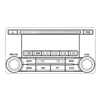
Describes the role of each key in different operating modes (Radio, CD, USB/iPod, AUX, Satellite).

Key Legend and Layout

Identifies keys and their corresponding numbers on the unit's layout.

Connectors

Connector Descriptions

Details the main antenna socket, power/speaker, IE-BUS/AUX, and USB connectors.

Pin Assignments

Lists pin numbers and signal names for each connector type.

System Configuration

System Diagram

Visualizes the system layout including external devices and the main unit.

Block Diagram

Signal and Power Flow

Illustrates signal, power, and control lines between internal components.

Disassembling Procedures

Initial Assembly Steps and Labels

Overview of assembling procedures and identifying parts like M012, M018, M019.

Component Assembly Part 1

Detailed steps for assembling M002, M010, M017, M005, and screw torque.

Component Assembly Part 2

Steps for fitting S2-DY, S2-PANEL, and securing FFC.

Component Assembly Part 3

Steps for assembling M003, M006, and ASSY-CHASSIS-B.

Component Assembly Part 4

Steps for assembling M004, M007, M008, M009, M011, M014.

Component Assembly Part 5

Steps for assembling M001, M013, M015, M016.

Rattle Sound Check

Procedure for checking rattle sounds by shaking the S2-PANEL.

Parts List

Parts for DY-1MU3R45-T

Lists reference numbers, part numbers, names, and pages for model DY-1MU3R45-T.

Parts for DY-1MU3R45-T-2

Lists reference numbers, part numbers, names, and pages for model DY-1MU3R45-T-2.

Electrical Parts List

Component Listings (Pages 18-24)

Comprehensive list of electrical components with part numbers and specifications.

Parts Layout on Printed Circuit Board

PCB-MAIN Component Placement (Parts Side)

Diagram showing the physical layout of components on the PCB-MAIN (parts side).

PCB-MAIN Component Placement (Pattern Side)

Diagram showing the physical layout of components on the PCB-MAIN (pattern side).

Schematic Diagram

PCB-MAIN Schematic

Detailed circuit diagram for the PCB-MAIN, showing component interconnections.

Voltage

Microcomputer Voltage Table

Lists terminal names, I/O, ACT, function, and voltage levels for the microcomputer.

Voltage Supply and Other ICs

Details voltage levels for various ICs and power supply inputs.

Voltage Tables by IC

Comprehensive voltage tables for DSP IC, Power IC, Microcomputer, and Voltage Supply.

Waveform

Signal Waveforms

Displays oscilloscope waveforms for key clock signals and data interfaces.

Related product manuals