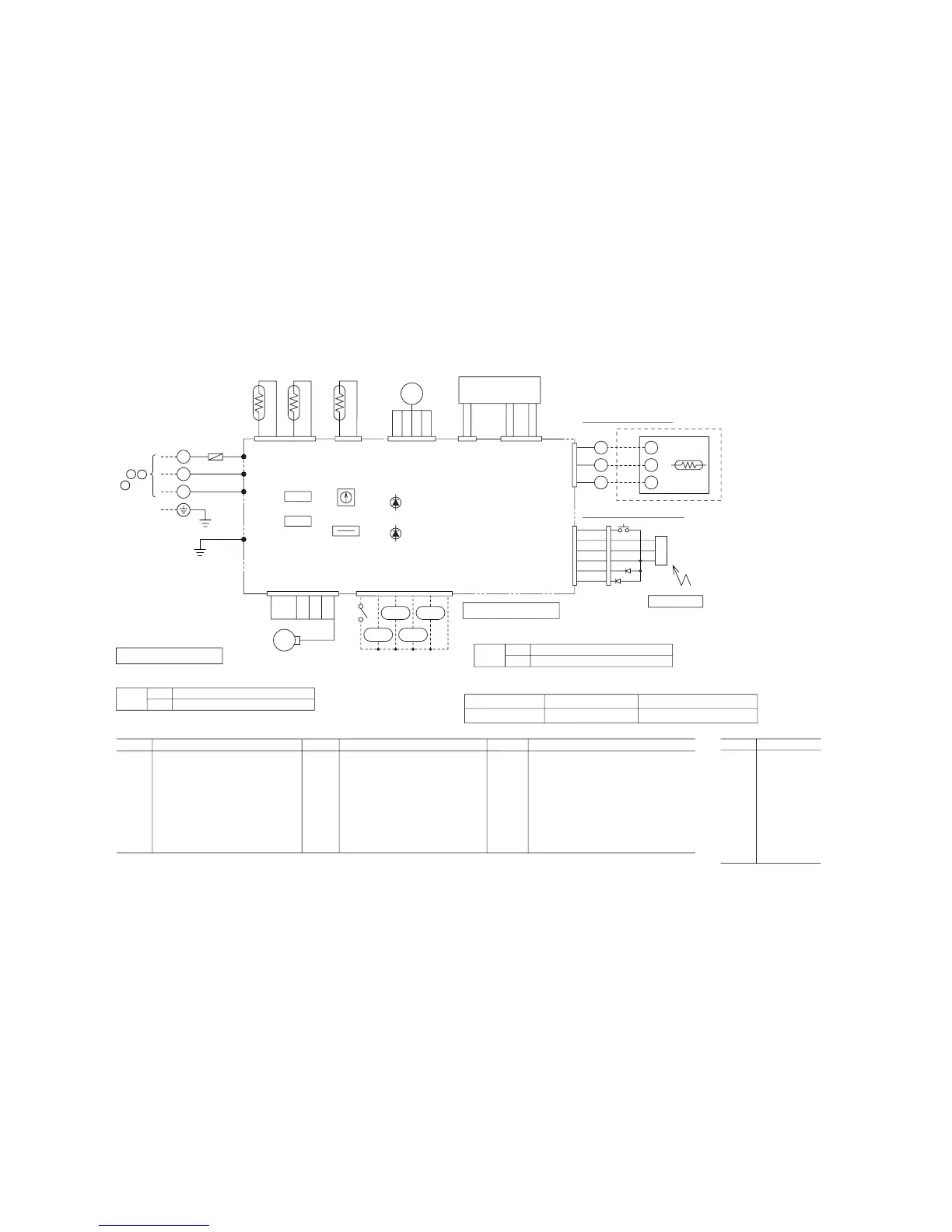
to outdoor unit
Power line
Signal line
1
3
2/N
Wireless specification
Wired specification
Remote controller
Remote
controller
ThC
X
X
CnB
Z
Y
Z
Y
TB1
FMI
SW
LED5
LED3
AMP
CnM
1
2/N
WH
RD RD
WH
Y
BK
BL
RD
BK
BK
BK
BK
BK
BK
CnW1
LED • R
LED • G
CnH
ThI-R1 ThI-A
CnN1
ThI-R2
1
2
3
1234
G
S
3
BL/WH
J
R
BL
P
BR
BK
BK
OR
RD
LM
12 3 4 5
CnJ
RD
WH
BK
RD
WH
BK
2
4
3
6
1
5
CnL
TB
SW9
SW5
SW2
J31
Y/GN
Y/GN
XR1
XR4
XR5
XR2
XR3
CnT
345621654321
Option
BR
BR
CnW2
12
TrI
220/
240V
14V17V
Printed circuit board
FMI
LM
ThI-A
ThI-R1
ThI-R2
ThC
SW
SW2
SW
5-3,4
Fan motor
Louver motor
Thermistor
Thermistor
Thermistor
Thermistor
Backup switch(ON/OFF)
Remote controller communication address
Filter sign
SW9-3
LED3
LED5
TrI
F
LED • R
LED • G
XR1
XR2
Emergency operation
Indication lamp(Green-Run)
Indication lamp
(Yellow-Inspection alert)
Transformer
Fuse
Indication lamp(Red)
Indication lamp(Green)
Operation output(DC12V output)
Heating output(DC12V output)
XR3
XR4
XR5
TB
CnA~Z
AMP
Thermo ON output(DC12V output)
Inspection output(DC12V output)
Remote operation input(volt-free contact)
Terminal block( mark)
Connector
Wirelss receiver
Mark Parts nameMark Parts nameMark Parts name
Meaning of marks
Color marks
BK
BL
BR
OR
RD
WH
Y
P
BL/WH
Y/GN
Black
Blue
Brown
Orange
Red
White
Yellow
Pink
Blue/White
Yellow/Green
Mark Color
RD
RD
435
F (3.15A)
Blower fan tap switch
Wired remote controller
SW9-4
ON
OFF
Fan control, powerful mode
Fan control, mild mode
J31
With
None
Wireless remote controller
Wired remote controller
Function number
A
Function description
B
Setting
C
1 Set SW9-4 provided on the indoor unit PCB to OFF.
01
Hi CEILING SET STANDARD
(Mild mode)
Use one of the two methods to set the fan tap.
When a wired remote controller is connected, none J31 provided
on the indoor unit PCB.
Note (1) “None” means that jumper wire is not provided on the PCB or the connection is cut.
Select the “STANDARD (Mild mode)” setting for “
C ” in #01 of “I/U FUNCTION
▲”
(indoor unit function) by using remote controller function setting.
2
 Loading...