1
2/N
3
C
To outdoor unit
Power wires
Signal wire
SW9
SW5
CnI2
CnR2
CnRI1
CnRI
CnI
CnR
CnH
CnH2
CnN3
CnNZ
CnN1
CnN6
CnN5
CnW0
CnW2 CnW1
SW2
LED
•
1
LED
•
2
RD
WH
BL
TB
1
2/N
3
Y/GN
Y/GN
Y/GN
F(3.15A)
F(0.16A)
FS
DM
X4
X6 X2
X1 X3
WHWH
BR
BR
BK
BK
BK
BK
BK
BK
RD/Y
BL/Y
BK
Y
OR
RD
RD
BK
BK
BR/Y
WH
RD
RDRD
RDRD
RD
RD
RD
RD
RD
RD
RD
RD
RD RD
RD
RD
RD
ThI-A ThI-R1 ThI-R2
XR3 XR1
XR5
XR2XR4
CnT
CnM3
CnF3
CnF3
CnG
CnS
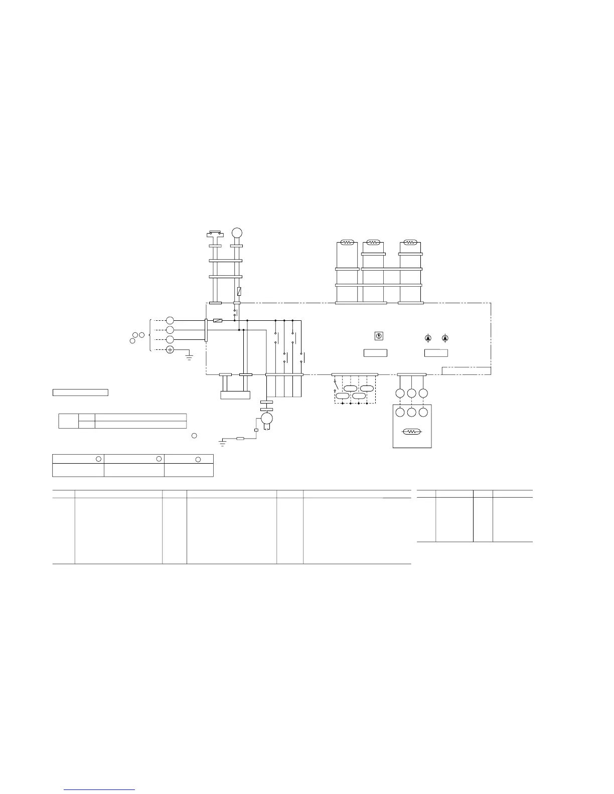
Option
CUH H M L
FMI1
CFI1
TrI
15V
220/
240V
Printed circuid board
FMI1
CFI1
DM
FS
ThI-A
ThI-R1
ThI-R2
ThC
Fan motor
Capacitor for FMI
Drain motor
Float switch
Thermistor
Thermistor
Thermistor
Thermistor
SW5-3,4
SW9-3
TrI
F
LED
•
1
LED
•
2
XR1
Filter sign
SW2
Remote control communications address
Emerqency operation
Transformer
Fuse
Indication lamp(Red:inspection)
Indication lamp(Green:normal operation)
Operation output(DC12V output)
XR2
XR3
XR4
XR5
X1,2,3,6
X4
TB
CnA~Z
mark
Heating output(DC12V output)
Thermo ON output(DC12V output)
Inspection output(DC12V output)
Remote operation input(volt-free contact)
Auxiliary relay(For FM)
Auxiliary relay(For DM)
Terminal block(
mark)
Connector(
□
mark)
Closed-end connector
Mark
Mark
Mark Parts name Parts name Parts name
Meaning of marks
Color marks
BK
BL
BL/Y
BR
BR/Y
Black
Blue
Blue/Yellow
Brown
Brown/Yellow
OR
RD
RD/Y
WH
Y
Y/GN
Orange
Red
Red/Yellow
White
Yellow
Yellow/Green
Mark Color
Mark Color
XYZ
XYZ
RD
RD
WH
WH
BK
BK
CnB
ThC
TB
Remote
controller
1
21 3 1
3421
65
432 1
123
1
3
579
3
5
Blower fan tap switch
SW9-4
ON
OFF
Fan control, high speed (High ceiling)
Fan control, standard
A
B
C
Function number Function description
Setting
Use one of the two methods to set the fan tap.
1Set SW9-4 provided on the indoor unit PCB to ON.
01
Hi CEILING SET
Hi CEILING 1
2Select the
“
Hi CEILING 1 (High-speed tap)
”
setting for
“
”
in #01 of
“
I/U FUNCTION
▲”
(Indoor unit fuction) by using
remote controller function setting.
 Loading...