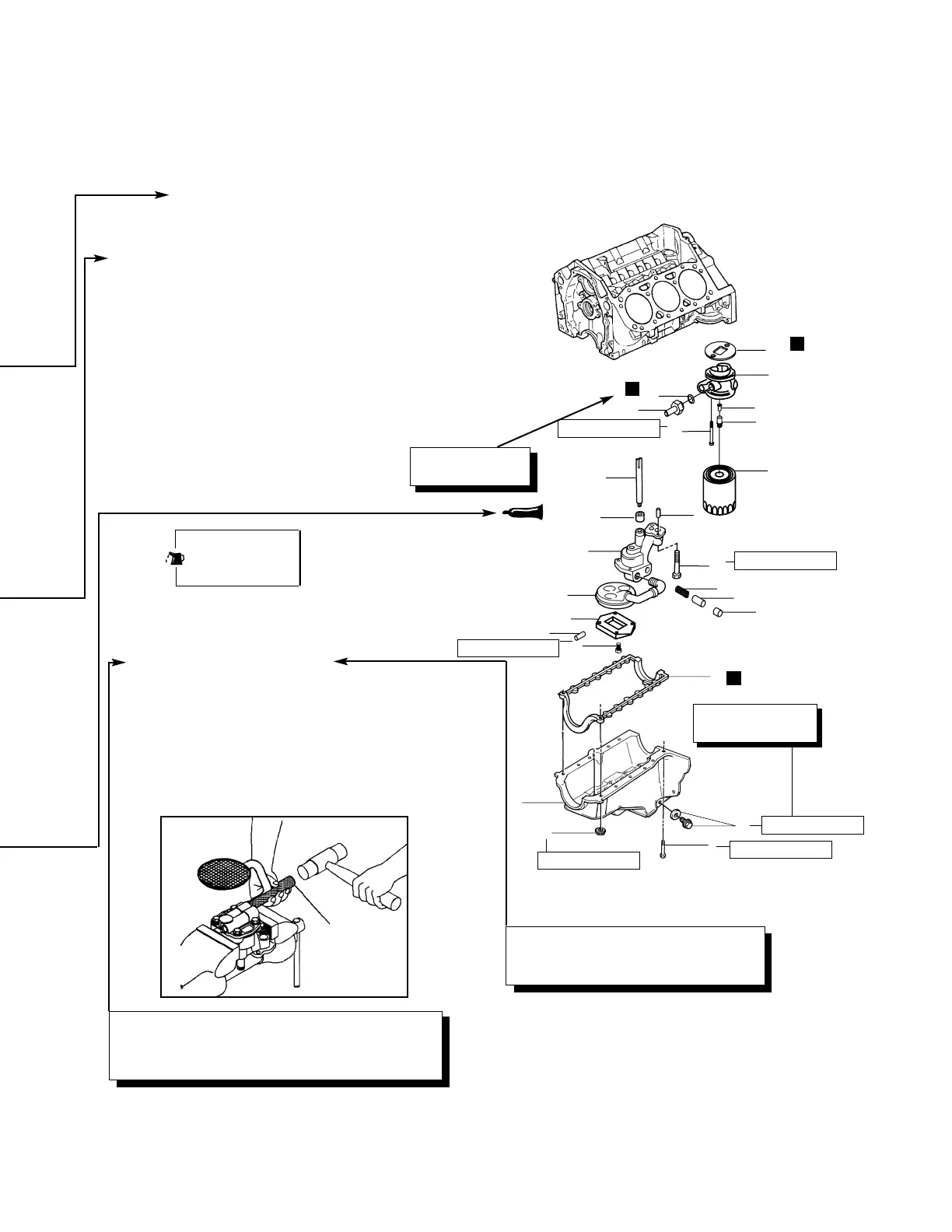
INSTALLATION OR REMOVAL SERVICE POINTS
Install the oil pump screen.
• If removed, replace the oil pump screen. The oil
pump screen must have a good press fit into the
oil pump body.
• Mount the oil pump in a soft jawed vise.
• Apply sealer to the end of the pipe.
• Use the (J 21882) and a soft-faced hammer to
tap the oil pump screen into the pump body. The
screen must align parallel with the bottom of the
oil pan when it is installed.
Removal steps
1. Plug
2. Nut
3. Bolt
4. Pan
5. Gasket
6. Bolt
7. Pin
8. Pump
9. Retainer
10. Shaft
11. Bolt
12. Pin
13. Cover
14. Screen
Lubricate all inter-
nal parts with
engine oil during
Unit: kgf-m (lb-ft) [N-m]
*kgf-m (lb-in.) [N-m]
T = 1.22 (106) [12]
Removal and Installation
➧
A
➧
➧
A
➧
Operating procedures, cautions, etc., on
removal, installation, disassembly and
reassembly are described.
Denotes tightening
torque.
This alphabetical letter corresponds to a part that is
indentified in the drawing on the first page of each
section. The letter appears during an explanation of
removal, installation, disassembly or reassembly steps.
Denotes
nonreusable part.
-III-
N
N
N
T = 9.14 (66) [90]
T = 2.08 (15) [20]
T = 2.49 (18) [25]
T = 2.49 (18) [25]
T = 2.49 (18) [25]
J 21882
 Loading...