System description
-
119
-
'10 • HM-T-149
Gas
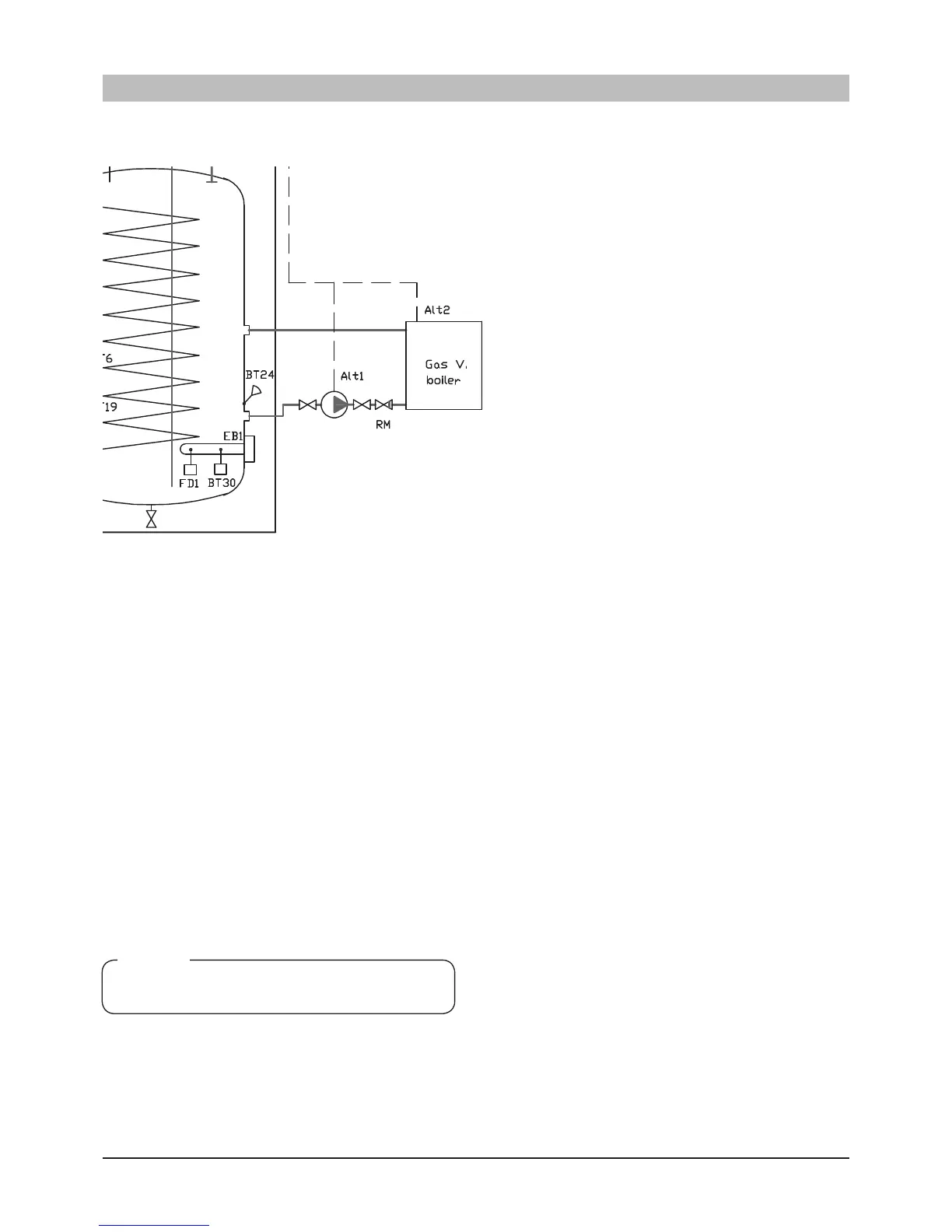
Function
Hydrolution engages additional heat source when the compressor
output is not sufcient for the house demand.
When the additional heat source is connected, valves QM 30
and QM31 shift to the heating system. Valve QN11 shunts in
the event of a heat demand on the ow line. Hot water can be
produced with the addional heat source.
Max temp should be 65°C out from the gas red boiler.
Control signal for additional heat source taken from terminal
block X3.
Jumper wire between X3:2-3 must be removed.
The control signal input is connected to terminal block X3:2
(230V), X3:4 (N).
Menu 9.2.8 set to External Line 1.
Alt 1: The gas boiler runs continuously. Indoor unit controls
the circulation pump.
Alt 2: Condensing gas boiler with internal circulation pump.
Indoor unit provides the gas boiler with start and stop signals.
↑ Connected to X3:2 and X3:4 with the jumper wire on X3:2-3 removed.
For details, see page 75.
NOTE
Maximum current on the terminal block X3 is 0.4A
External heat source
 Loading...


