EasyManuals Logo

Mitsubishi HMA100V Technical Manual

Mitsubishi HMA100V
305 pages
To Next Page IconTo Next Page
To Previous Page IconTo Previous Page
Page #72 background imageLoading...
Page #72 background image
Installation
-
71
-
'10 HM-T-149
L N
1 2 3
L N 2 3 PE
(AMS 10-12:-X1)
Outdoor unit
brown
blue
black
grey
yellow/green
TB
X2
Indoor unit
power cable
communication cable
LN
1 2 3
NL
2 3 PE
Outdoor unit
brown
blue
black
grey
yellow/green
5x2.5 mm
2
TB
X2
Indoor unit
Main circuit breaker size setting (R24 on AA22)
(Applicable only in case of 3 phase power supply)
The size of the property’s main circuit breaker is set using the
knob(R24)onthecircuitlimiterPCB,(AA22).Thesettingcan
be read in Menu 8.3.4.
Main fuse rating Knob position
16 16
20 20
25 25 (factory setting)
35 35
50 50
63 63
Setting max power, electric heater (R25 on AA22)
Setting of the different maximum immersion heater outputs is
madeusingtheknob(R25)onthePCB(AA22).Setvalue
displayed in Menu 8.3.2. The following table only applies
whenMenu9.2.8Add.heattypeissetto“Internalpower”
(factory setting).
Whentheoutdoorunitisinoperation,maximumheateroutput
is limited to 6.0 kW.
Max load
phase (A)*
HMA100V HMA100VM HMS140V
Max. electric
power
(Menu 8.3.2)
Knob positionImmersion
heater, out-
put (kW)
152A4.0
153B6.0
15
29
30
30
25
25
254C
(factory setting)
9.0
*Onlyappliesto3phaseconnection.
Setting max boiler temperature (R26 on AA22)
The setting of the different maximum boiler temperatures is
madeontheknob(R26)onthePCB(AA22).Setvaluedisplayed
in Menu 9.3.1.
Knob positionBoiler temperature
A55
B60
C (factory setting)65
D65
E65
F65
Iutdoor unit installation
<
FDCW71VNX
>
<
FDCW100VNX, 140VNX
>
power cable
sensor cable
sensor cable
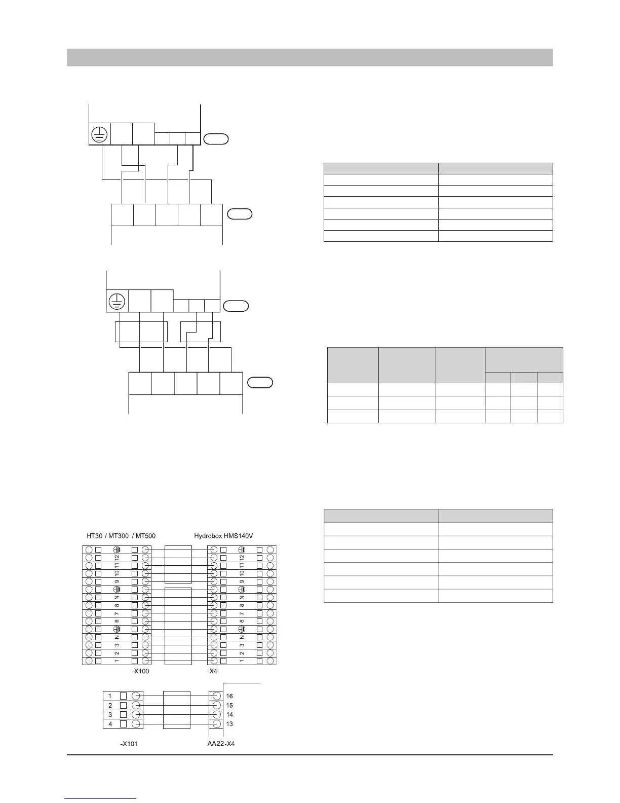
Connection between indoor unit and tank
(HMS140V only)
Cable between indoor unit and tank must be connected between
the terminal block (X4) in indoor unit and the terminal block
(X100) in tank,theterminalonPCB(AA22-X4)inindoorunit
and the terminal block (X101) in tank respectively.
Connect the terminals as shown in the following figure.

Table of Contents

Other manuals for Mitsubishi HMA100V

Questions and Answers:

Question and Answer IconNeed help?

Do you have a question about the Mitsubishi HMA100V and is the answer not in the manual?

Mitsubishi HMA100V Specifications

General IconGeneral
BrandMitsubishi
ModelHMA100V
CategoryHeat Pump
LanguageEnglish

Related product manuals