Chapter 8 Clutch and driveline
a-9
\ -w
Mating marks
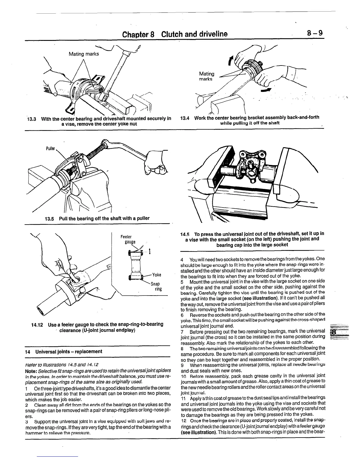
13.3 With the cente; bearing and &&haft mounted S?cUrely in
a vise, remove the center yoke nut
.,A j
\
13.4 Work the center bearing bracket assembly back-and-forth
while pulling it off the shaft
13.5 Pull the bearing off the shaft with a puller
14.12 Use a feeler gauge to check the snap-ring-to-bearing
’ clearance (U-joint journal endplay)
14 Universal joints - replacement
Refer to illustrations 14.5 and 14.12
Note:
Selective fit snap-rings are used to retain the universaljointspiders
in the yokes. In order to maintain the driveshaft balance, you must use re-
placement snap-rings of the same size as originally used.
1 Onthree-jointtypedriveshafts, it’sagoodideatodismantlethecenter
universal joint first so that the driveshaft can be broken into two pieces,
which makes the job easier.
2 Clean away all dirt from the ends of the bearings on the yokes so the
snap-rings can be removed with a pair of snap-ring pliers or long-nose pli-
ers.
3 Support the universal joint in a vise equipped with soft jaws and re-
move the snap-rings. If they are very tight, tap the end of the bearing with a
hammer to relieve the pressure.
14.5 To press the universal joint out of the driveshaft, set it up in
a vise with the small socket (on the left) pushing the joint and
bearing cap into the large socket
4 You will need two sockets to remove the bearings from the yokes. One
shoirld be large enough to fit into the yoke where the snap-rings were in-
stalled and the other should have an inside diameter just large enough for
the bearings to fit into when they are forced out of the yoke.
5 Mount the universal joint in the vise with the large socket on one side
of the yoke and the small socket on the other side, pushing against the
bearing. Carefully tighten the vise until the bearing is pushed out of the
yoke and into the large socket (see
illustration).
If it can’t be pushed all
the way out, remove the universal joint from the vise and use apairof pliers
to finish removing the bearing.
6 Reverse the sockets and push out the bearing on the other side of the
yoke. This time, the small socket will be pushing against the cross-shaped
universal joint journal end.
7 Before pressing out the two remaining bearings, mark the universal
joint journal (the cross) so it can be installed in the same position during
reassembly. Also mark the relationship of the yokes to each other.
8 The two remaining universal joints can be disassembled following the
same procedure. Be sure to mark all components for each universal joint
so they can be kept together and reassembled in the proper position.
9 When reassembling the universal joints, replace all needle bearings
and dust seals with new ones.
10 Before reassembly, pack each grease cavity in the universal joint
journals with a small amount of grease. Also, apply a thin coat of grease to
thenewneedle bearing rollersand therollercontactareason theuniversal
joint journal.
11 Apply athin coat of grease to the dust sea\ lips and install the bearings
and universal joint journals into the yoke using the vise and sockets that
were used to remove the old bearings. Work slowly and be very careful not
to damage the bearings as they are being pressed into the yokes.
12 Once the bearings are in place and properly seated, install the snap-
ringsandchecktheclearance (U-jointjournalendplay) withafeelergauge
(see illustratidn).
This is done with both snap-rings in place and the bear-
 Loading...


