Electrical installation
General
Indoor unit must be installed via an isolator switch in
accordance with the local codes and regulations.
Otherelectricalequipment,excepttheoutdoorsensors,current
transformers and outdoor unit are ready connected at the factory.
■ Disconnect the indoor unit and outdoor unit before
insulation testing the house wiring.
■ Forrecommendedfuseratings,refertothefollowingtable.
Indoor Outdoor 230V 1AC 230V 3AC 400V 3NAC
HMA100V
FDCW71VNX 50A
-
16A
FDCW100VNX 50A
-
16A
HMA100VM
FDCW71VNX
-
32A
-
FDCW100VNX
-
32A
-
HMS140V FDCW140VNX 63A
-
25A
■ Ifthe building is equipped with an earth-fault breaker,
Hydrolution should be equipped with a separate one.
■ Connectionmustnotbecarriedoutwithoutthepermission
of the electricity supplier and under the supervision of a
qualiedelectrician.
■ Forinterconnectioncablebetweenindoorunitandoutdoor
unit,thesizeshownonthetablebelowisrecommended.
Indoor Outdoor Cable size
HMA100V
FDCW71VNX
FDCW100VNX
5×2.5 mm
2
HMA100VM
FDCW71VNX
FDCW100VNX
5×2.5 mm
2
HMS140V FDCW140VNX
3×6 mm
2
(powercable*1)
3×1.5 mm
2
(communication cable)
*
1 Maximum current on power cable is 25A.
Choose suitable size in accordance with regulations.
*
2
Maximumcurrentonpowercableis26Afor230V1AC,9A
for 400V 3NAC.
Choose suitable size in accordance with regulations.
■ Outdoorunitisequipped withasinglephasecompressor.
This means that phase L3 is loaded with up to 15A for
FDCW71VNXandFDCW100VNX,25AforFDCW140VNX
during compressor operation.
NOTE
Electrical installation and service must be carried out
under the supervision of a qualied electrician.
Electrical installation and wiring must be carried out
in accordance with the stipulations in force.
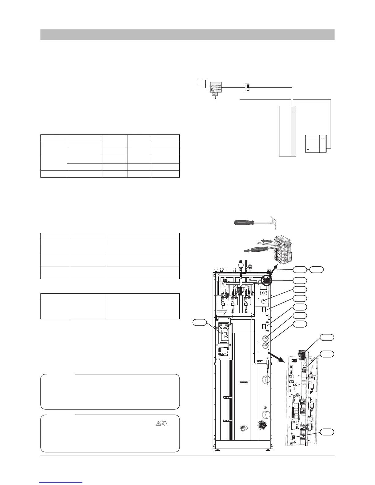
Principle diagram, electrical installation
 Loading...

