APPENDICES
Appendix 2 Special Register List
App - 74
9
Parameters
10
Device Explanation
11
CPU Module Processing
Time
12
Procedure for Writing
Program to CPU ModuleAppendicesIndex
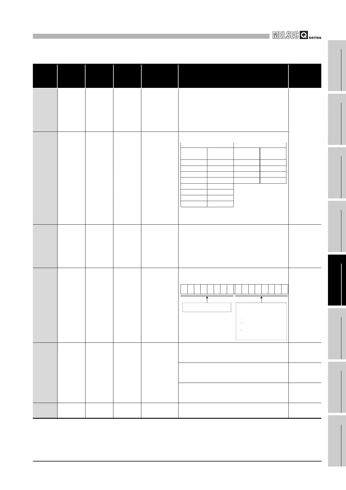
TableApp.28 Special register
ACPU
Special
Register
Special
Register
after
Conversion
Special
Register for
Modification
Name Meaning Details
Corresponding
CPU
D9000 SD1000
–
Fuse blown
Number of module
with blown fuse
• When fuse blown modules are detected, the first I/O number of the
lowest number of the detected modules is stored in hexadecimal.
(Example: When fuses of Y50 to 6F output modules have blown,
"50" is stored in hexadecimal)
To monitor the number by peripheral devices, perform monitor
operation given in hexadecimal.
(Cleared when all contents of SD1100 to SD1107 are reset to 0.)
• Fuse blow check is executed also to the output modules of remote
I/O stations.
QnA
Qn(H)
QnPH
D9001 SD1001
–
Fuse blown
Number of module
with blown fuse
• Stores the module numbers corresponding to setting switch
numbers or base slot numbers when fuse blow occurred.
• For the remote I/O station, the value of (module I/O No./10H) + 1 is
stored.
D9002 SD1002
–
I/O module
verify error
I/O module verify
error module number
• If I/O modules, of which data are different from data entered, are
detected when the power is turned on, the first I/O number of the
lowest number unit among the detected units is stored in
hexadecimal. (Storing method is the same as that of SD1000.)
To monitor the number by peripheral devices, perform monitor
operation given in hexadecimal.
(Cleared when all contents of SD1116 to SD1123 are reset to 0.)
• I/O module verify check is executed also to the modules of remote
I/O terminals.
QnA
Qn(H)
QnPH
D9004 SD1004
–
MINI link
master module
errors
Stores setting status
made at parameters
• Error status of the MINI(S3) link detected on loaded AJ71PT32(S3)
is stored.
QnA
D9005 SD1005
–
AC DOWN
counter
Number of times for
AC DOWN
• When the AC power supply module is used, 1 is added at
occurrence of an instantaneous power failure of within 20ms.
(The value is stored in BIN code.) It is reset when the power supply
is switched from OFF to ON.
QnA
Qn(H)
QnPH
• When the DC power supply module is used, 1 is added at
occurrence of an instantaneous power failure of within 10ms.
(The value is stored in BIN code.) It is reset when the power supply
is switched from OFF to ON.
Qn(H)
QnPH
• When the DC power supply module is used, 1 is added at
occurrence of an instantaneous power failure of within 1ms.
(The value is stored in BIN code.) It is reset when the power supply
is switched from OFF to ON.
QnA
D9008 SD1008 SD0
Self-diagnostic
error
Self-diagnostic error
number
• When error is found as a result of self-diagnosis, error number is
stored in BIN code.
QnA
Qn(H)
QnPH
Base unit slot
No.
Stored dataStored dataSetting switch
Extension base unitI/O module for A0J2
0
1
2
3
4
5
6
7
0
1
2
3
4
5
6
7
0
1
2
3
4
5
6
7
b15 b8 b7 b0
Bits which correspond to faulty
AJ71PT32(S3) are turned on.
76543218 7 6543 218
to to
Bits which correspond to the signals of
AJ71PT32(S3), shown below, are
turned on as the signals are turned
on.
Hardware error (X0/X20)
MINI(S3) link error datection
(X6/X26)
MINI(S3) link
communication error
(X7/X27)
 Loading...