14 - 4
MELSEC-Q
14 DEDICATED INSTRUCTIONS
[Control data]
Device
Item
Setting data Setting range
Setting side
( 1)
(S)+0
System area
– – –
(S)+1
Complete status
The state at the time of completion is stored.
•
0 : Normal completion
•
Other than 0 : Abnormal completion (error code)(
2)
– System
(S)+2
Signal received from
servo amplifier
The following signal states taken in from the servo
amplifier to the input module are written.
• b0: ABS data bit 0
• b1: ABS data bit 1
• b2: Transmission data READY flag
b0: 0/1
b1: 0/1
b2: 0/1
User
(S)+3
Signal transmitted to
servo amplifier
The ON/OFF states of the following data which are
calculated using the dedicated instructions by the
"signals received from the servo amplifier" and output to
the servo amplifier are stored.
• b0: Servo amplifier ON
• b1: ABS transfer mode
• b2: ABS request flag
–
System
(S)+4
Status
Status of communication with servo amplifier
• 0 : Communication completed
(Set by user at communication start)
• Other than 0 : During communication (System stores)
0 User/system
(S)+5 to
(S)+7
System area
–
–
–
1: The data on the setting side is as follows.
• User : Data before the execution of dedicated instructions is stored by user.
• System : Data after the execution of dedicated instruction is stored by CPU module.
2: Refer to Section 15.3 for error codes at abnormal completion.
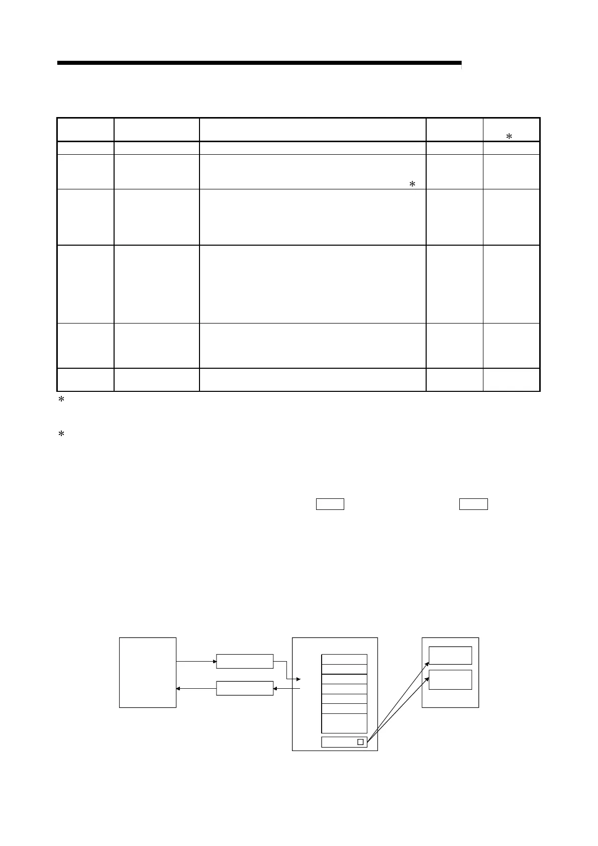
[Functions]
(1) The positioning data is read from the servo amplifier capable of processing the
absolute positions of the axes to be set (See below), and the values converted with
respect to a unit are stored in "
Md.20
Current feed value" and "
Md.21
Machine
feed value" area of the QD75.
• Z.ABRST1: Axis 1
• Z.ABRST2: Axis 2
• Z.ABRST3: Axis 3
• Z.ABRST4: Axis 4
For absolute position detection system, carry out the absolute position restoration
operation each time the power is turned ON or CPU module is reset.
(S)+0
(S)+1
(S)+2
(S)+3
(S)+4
(S)+5
to
(S)+7
Control data
Current
feed value
Input module
Output module
Servo amplifier
Current value data
CPU module
QD75
Z.ABRST
Machine
feed value
 Loading...
