1-10
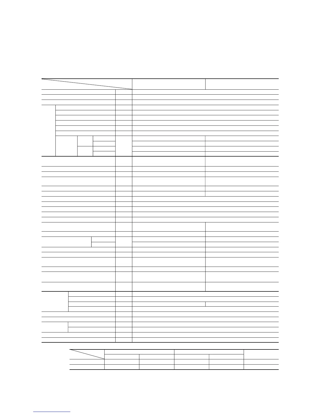
Model SRK50A (Indoor unit)
SRC50HA (Outdoor unit)
Item
Model
SRK50A SRC50HA
Cooling capacity
(1)
W 4500
Heating capacity
(1)
W 5700
Power source 1 Phase, 220/230/240V, 50Hz
Cooling input kW 1.79
Running current (Cooling) A 8.4/8.0/7.7
Heating input kW 1.83
Running current (Heating) A 8.5/8.1/7.9
Inrush current A 39/41/42
COP (In cooling) 2.51
Cooling
Sound level Hi : 44 Lo : 37 51
Noise level
Power level
dB
Hi : 58 Lo : 51 65
Heating
Sound level Hi : 45 Lo : 38 53
Power level Hi : 59 Lo : 52 67
Exterior dimensions
Height x Width x Depth
mm 298‚798‚203 640‚850‚290
Color Stucco white Stucco white
Net weight kg 10 45
Refrigerant equipment
Compressor type & Q’ty
– RM5523GNE4 (Rotary type) x 1
Motor kW – 1.7
Starting method – Line starting
Heat exchanger Louver fins & grooved tubing
Refrigerant control Capillary tubes
Refrigerant
(3)
kg R22 1.45
Refrigerant oil R 0.7 (BARREL FREEZE 32SAM)
Defrost control MC control
Air handling equipment
Fan type & Q’ty
Tangential fan x 1 Propeller fan x 1
Motor W 23 35
Air flow (at High) (Cooling) 11 39
(Heating)
CMM
13 39
Air filter, Q’ty Polypropylene net (washable) x 2 –
Shock & vibration absorber – Cushion rubber (for compressor)
Operation control
Operation switch
Wireless–Remote controller –
Room temperature control MC. Thermostat –
Pilot lamp RUN (Green), TIMER (Yellow),
–
ECONO (Orange), HI POWER (Green)
Safety equipment
–
Dome mounted protector (for compressor)
Internal thermostat (for fan motor)
O.D mm(in) Liquid line: ø6.35 (1/4") Gas line: ø12.7 (1/2")
Connecting method Flare connecting
Attached length of piping Liquid line: 0.5m Gas line: 0.43m –
Insulation Necessary (Both sides)
Drain hose Connectable
Power source cord 3m (3 cores with Earth)
Connection Size x Core number 1.5mm
2
x 5 cores (With Earth)
wiring
Connecting method Terminal block (Screw fixing type)
Accessories (included) Mounting kit
Optional parts –
Notes (1) The data are measured at the following conditions.
Item Indoor air temperature Outdoor air temperature
Standards
Operation DB WB DB WB
Cooling 27ºC 19ºC 35ºC 24ºC ISO-T1, JIS C9612
Heating 20ºC – 7ºC 6ºC ISO-T1, JIS C9612
(2) The operation data are applied to the 220V, 230V or 240V districts respectively
(3) The refrigerant quantity to be charged includes the refrigerant in 7 m connecting piping. (Purging is not required even in the short piping.)
If the piping length is longer. (When it is 7 to 15 m, add 20 g refrigerant per meter.)
(4) When the unit is operated in cooling or dehumidification mode at the outside air temperature of 1ºC and less, there is a possibility that water leakage
occurs at the indoor unit.
Operation data
(1)
Refrigerant
piping
 Loading...