-
37
-
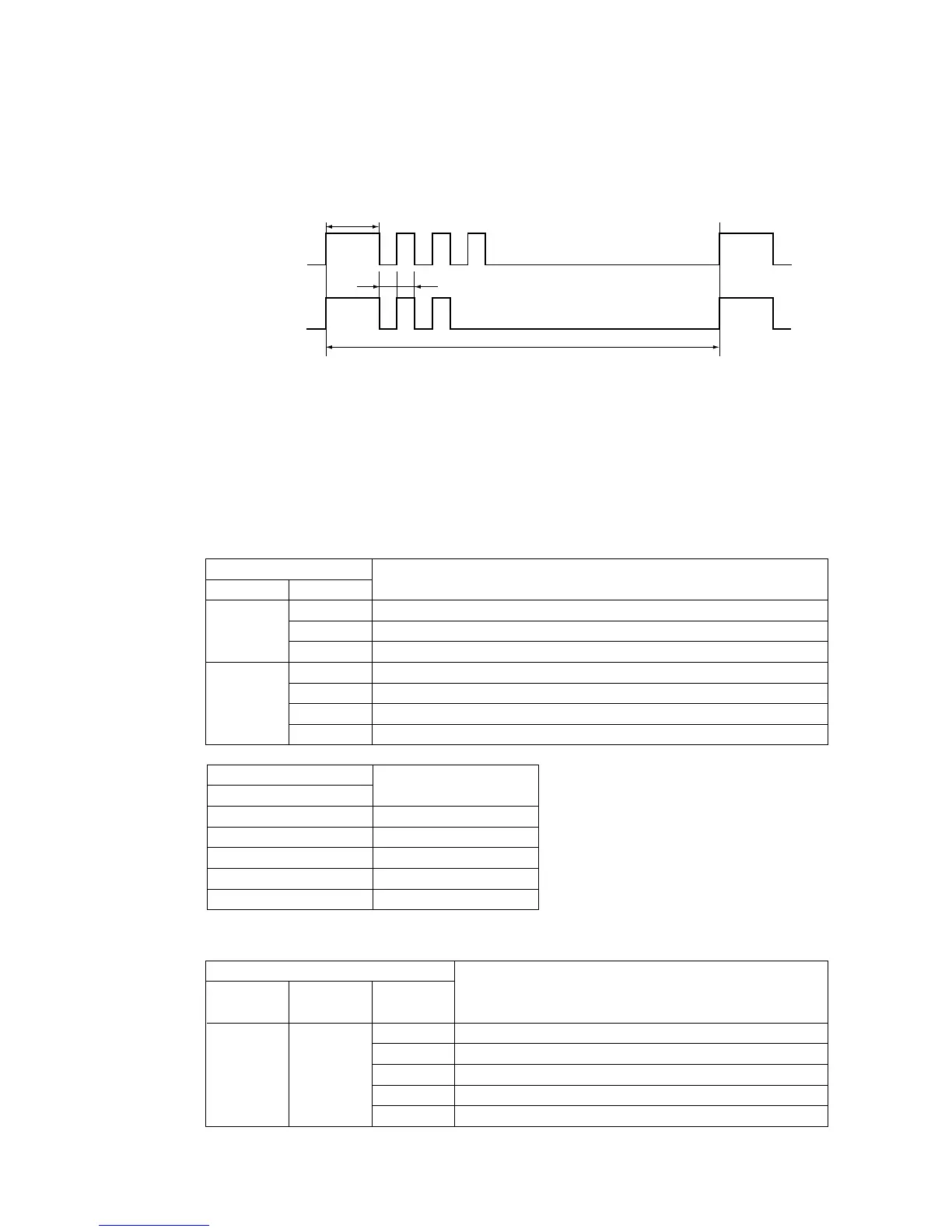
*3: To count the number of flashes in the service mode, count the number of flashes after the lamp lights up for 1.5 second
initially (start signal). (The time that the lamp lights up for 1.5 second (start signal) is not counted in the number of
flashes.)
*4:
When in the service mode, when the remote controller’s settings (operation switching, fan speed switching, temperature
setting) are set as shown in the following table and sent to the air conditioner unit, the unit switches to display of service data.
1 Self-diagnosis data
What are Self- ...... These are control data (reasons for stops, temperature at each sensor, remote controller information)
diagnosis Data? from the time when there were error displays (abnormal stops) in the indoor unit in the past.
Data from up to 5 previous occasions are stored in memory. Data older than the 5th previous occasion are erased.
The temperature setting indicates how many occasions previous to the present setting the error display
data are and the operation switching and fan speed switching data show the type of data.
Remote controller setting
Contents of output data
Fan speed switching
MED
HI
AUTO
LO
MED
HI
AUTO
Displays the reason for stopping display in the past (error code).
Displays the room temperature sensor temperature at the time the error code was displayed in the past.
Displays the indoor heat exchanger sensor temperature at the time the error code was displayed in the past.
Displays the remote controller information at the time the error code was displayed in the past.
Displays the outdoor temperature sensor temperature at the time the error code was displayed in the past.
Displays the outdoor heat exchanger liquid pipe sensor temperature at the time the error code was displayed in the past.
Displays the discharge pipe sensor temperature at the time the error code was displayed in the past.
Cooling
Operation switching
Heating
Remote controller setting
Indicates the number of
occasions previous to the present
the error display data are from.
Temperature setting
21°C
22°C
23°C
24°C
25°C
1 time previous (previous time)
2 times previous
3 times previous
4 times previous
5 times previous
Remote controller setting
Fan speed
switching
Operation
switching
Displayed data
Temperature
setting
21°C
22°C
23°C
24°C
25°C
Displays the reason for the stop (error code) the previous time an error was displayed.
Displays the reason for the stop (error code) 2 times previous when an error was displayed.
Displays the reason for the stop (error code) 3 times previous when an error was displayed.
Displays the reason for the stop (error code) 4 times previous when an error was displayed.
Displays the reason for the stop (error code) 5 times previous when an error was displayed.
Cooling MED
(Example)
0.5 sec.
1.5 sec.
Run lamp
(10’s digit)
Timer lamp
(1’s digit)
11-second interval
0.5 sec.
OFF
ON
OFF
ON
• In the case of current safe (heating CT1) (example: stop code “32”)
The run lamp (10’s digit) flashes 3 times and the timer lamp (1’s digit) flashes 2 times.
3 × 10 + 2 × 1 = 32 → From the table, read the instructions for error code 32, “current safe (heating CT1).
 Loading...