DS
+
-
~~
J
N
L
CC
11
9
7
3
1
5
3
1
Option
XR1
XR2
XR3
XR4
XR5
CNE
CNFCNM
CNX
CNY
CNT
CNG
SM
LM1
LM2
HA
J
RD
Y/GN
G
Y/GN
BK
2/N
1
WH
3
2/N
1
3
L
N
RD
Y/GN
BK
R/LS/N
WH
WH
RD
BK
1
3
Y
BL
4
5
6
ZNR
ZNR
F
250V
3.15A
F
250V
3.15A
Terminal block
TB TB
XZ
Y
XZ
Y
RD
WH
BK
BK
Color symbol
Meaning of marks
Symbol
CM
F
FM
I
FM
O
SM
LM
1,2
Th
1
Th
2
Th
3
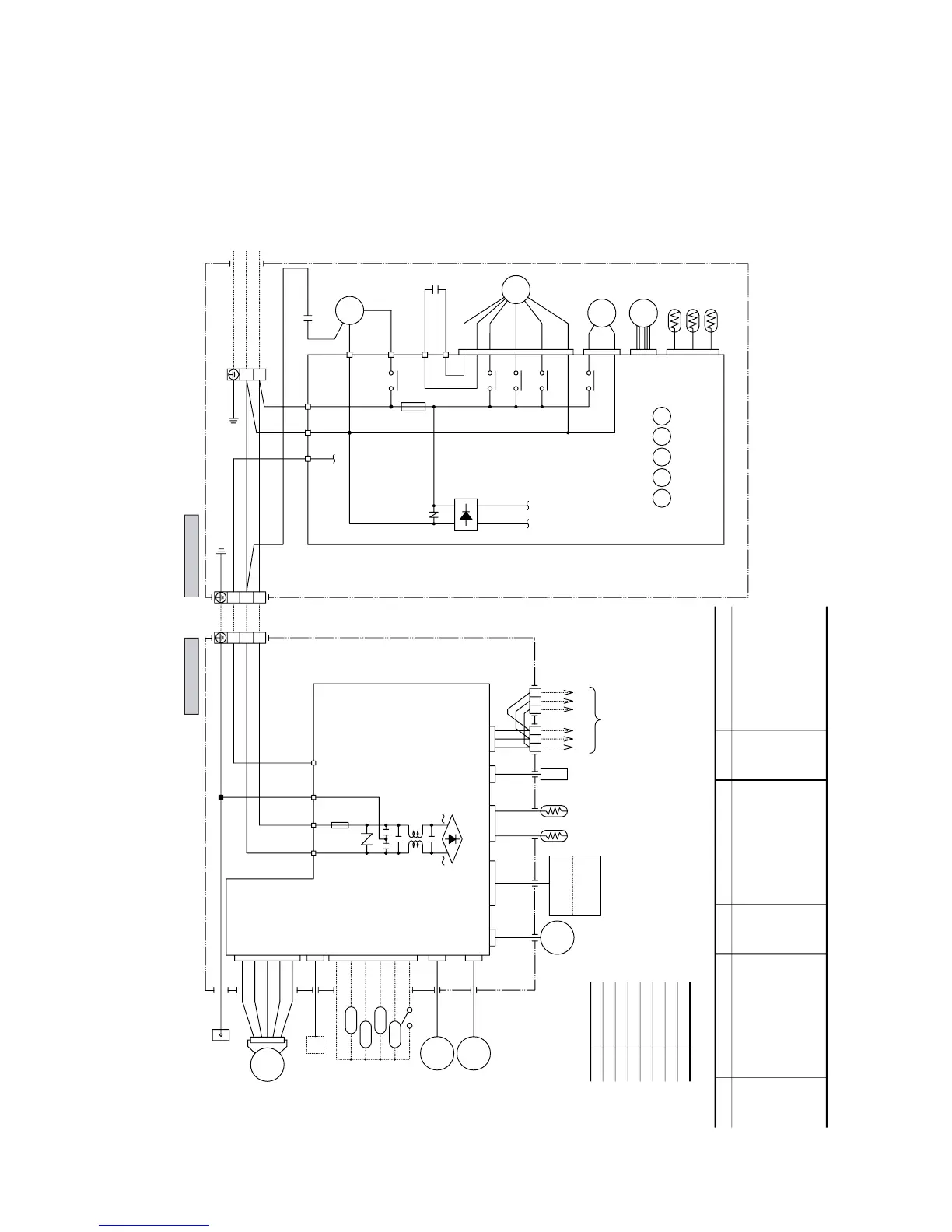
Compressor motor
Fuse
Fan motor(Indoor)
Fan motor(Outdoor)
Flap motor
Louver motor
Room temp.sensor
Heat exch.sensor(Indoor unit)
Humidity sensor
Capacitor for FM
O
Terminal block
Operation indication (DC12)
Heating indication (DC12)
ON indication for CM(DC12)
Check indication (DC12)
Distant operation
Heat exch.sensor(Outdoor unit)
Outdoor air temp.sensor
Discharge pipe temp.sensor
Varistor
4 way valve(coil)
Electronic expansion valve
Diode stack
Auxiliary relay
Capacitor for CM
Th
4
Th
5
Th
6
ZNR
20S
EEV
DS
52
X1~5
CC
CF
O
TB
XR1
XR2
XR3
XR4
XR5
Parts name
BL
OR
Y/G
Black
Blue
Orange
Yellow/Green
WH White
RD Red
GR Green
Y Yellow
Parts name Parts nameSymbol Symbol
BK
WH
RD
WH
RD
WH
OR
Y
RD
BL
BK
WH
BK
Y
Y
CM2
CM1
W
V
U
52X1
52X3
52X4
52X5
52X2
Power Source
1 Phase
220-240V 50Hz
To wired
remote
control
(Option)
Heat
exchanger
Outdoor unit
Indoor unit
R-AMP
Wireless
Display
Printed circuit
board
Printed circuit
board
CNU
JEM-A
CNB
CNU
CNB
CNE
CNG
FM
I
CM
20S
EEV
FMo
CF
O
52X
1
52X
2
52X
3
52X
4
52X
5
Th4
Th5
Th6
Th3Th2Th1
 Loading...