-
48
-
(b) Indoor unit fan motor check procedure
This is a diagnostic procedure for determining if the indoor unit’s fan motor or the circuit board is broken down.
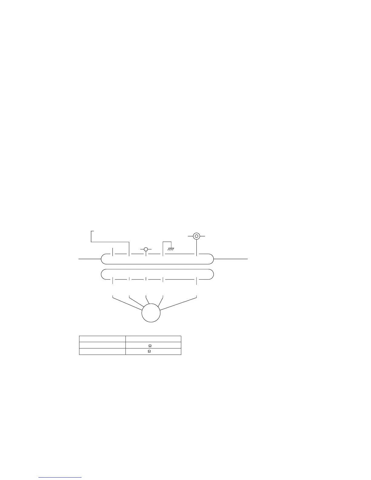
1) Indoor unit printed circuit board output check
a) Turn off the power.
b) Remove the front panel, then disconnect the fan motor lead wire connector.
c) Turn on the power. If the unit operates when the ON/OFF button is pressed, if trouble is detected after the voltages in
the following figure are output for approximately 30 seconds, it means that the circuit board is normal and the fan
motor is broken down.
If the voltages in the following figure are not output at connector pins No. 1, 4 and 5, the indoor unit’s circuit
board has failed and the fan motor is normal.
2) DC Fan motor resistance check
Notes (1) Remove the fan motor and measure it without power connected to it.
Notes (2) If the measured value is below the value when the motor is normal, it means
that the fan motor is faulty.
123456
123456
FM
I
DC15V
Indoor unit
circuit board
DC 308~336V
DC several V
(4~6 V)
CNU
(–)
GND
Blue
Yellow
White
Black
Red
Measuring Point Resistance when Normal
1 – 3 (Red – Black)
25 M
or higher
4 – 3 (White – Black) 30 k
or higher
(8) Checking the indoor electrical equipment
(a) Indoor unit circuit board check procedure
1) Press the unit’s ON/OFF button for 5 seconds or longer (a beep which indicates receiving will be emitted). Then check
the following items.
1 The indoor unit’s fan motor runs.
2 The run light lights up.
2) There should be voltage (AC 220-240 V) between terminals 1 and 2 on the terminal block.
With the analog tester set in the DC 30 V range, if the voltage at 2 (+) and 3 (-) is measured, the needle oscillates at
about 12V.
3) It is possible to run and stop the unit using the remote control. (The hot keep function is activated.)
If operation is as described above, the indoor unit’s board is normal.
Note (1) Check the voltage on the terminal block.
● Power supply : Between 1-2 (AC 220-240V)
● Signal : Between 2-3 (Changing between DC 0-Approx. 12V)
 Loading...